Hey guys, it’s a pita to pull the relay and throw the jumper wire in for my ic pump and vmp HE fans all the time. Is there anyway to wire a switch to do this from the cockpit and still maintain the relay to use as normal?
You are using an out of date browser. It may not display this or other websites correctly.
You should upgrade or use an alternative browser.
You should upgrade or use an alternative browser.
*How to Solved - Custom IC jumper switch
- Thread starter RazorGTP
- Start date
Anything can be done!

Ok sir first off, you are a legit guru.
Second, how can I do this with the ic pump and he fans? Can you draw a rudimentary schematic?
Is the relay switched on using power or ground and just add a switch to whatever it needs in the control side?
Last edited:
that is a really sweet setup you have there.
Ok sir first off, you are a legit guru.
Thanks.... I think...lol...!
Second, how can I do this with the ic pump and he fans? Can you draw a rudimentary schematic?
Is the relay switched on using power or ground and just add a switch to whatever it needs in the control side?
I will reply this weekend. I have a 3-ring binder with all my schematics, but I have not organized them yet. The circuits for my upper console panel is only the beginning of everything I've wired on my car. My binder is about one inch thick.
that is a really sweet setup you have there.
Thank you sir!
Willie
Thanks.... I think...lol...!
I will reply this weekend. I have a 3-ring binder with all my schematics, but I have not organized them yet. The circuits for my upper console panel is only the beginning of everything I've wired on my car. My binder is about one inch thick.
Thank you sir!
Willie
Yes that’s a legit compliment. Lol
Wow that’s quite the amount of projects you’ve done! I see in your sig it’s on an 08 gt500? As far as you know would a 13’ be the same? That would be great thanks!
Willie honored me with a ride in this monster... it is every bit the bad ass ride it seems it is!Ok sir first off, you are a legit guru.
Second, how can I do this with the ic pump and he fans? Can you draw a rudimentary schematic?
Is the relay switched on using power or ground and just add a switch to whatever it needs in the control side?
Willie honored me with a ride in this monster... it is every bit the bad ass ride it seems it is!
Haha that’s awesome!
....I see in your sig it’s on an 08 gt500? As far as you know would a 13’ be the same?
As far as the add-on wiring, yes, the same. The only differences, if any, would be location of the factory components and possibly the wiring color.
My suggestion if you haven't already, is to get factory wiring schematics for your year. You would use this as the basis for any and all electronic mods / add ons, etc.
To add the manual IC pump override switch, I tee'd into the Dark Blue / Yellow wiring that runs from the pump relay to the PCM at the base of the relay. Run this new wire to the switch, and ground the other switch terminal. This is assuming your switch is NOT lighted, which makes this circuit as simple as can be. I used 22ga, multi-stranded wire.
....how can I do this with the ic pump and he fans?
Okay, so assume you already have fans. We can wire these countless ways, depending on how you want them to work. On my car, I wired them to run when the pump is running AND I can also switch them on manually, as you've seen the switch for this in my pic. Can you describe what you want?
In addition to my switches, I installed one LED for the pump and one for each fan. When lit, they tell me that the circuit is working and voltage is received at the pump / right side fan / left side fan. These LEDs work independently of my manual switches. For example, when the PCM commands the pump to run, thie LED lights, regardless of switch position. Purely not necessary but it sure helps when problem solving and also knowing that the pump and/or fans are running when cruising down the boulevard.... you certainly can't hear them.... I have two similar LED's that tell me the coolant fan is running on low or high speed also.
Can you draw a rudimentary schematic?
Yes, if my description above isn't sufficient.
Willie
Last edited:
Click on the quote dialog box as i answered in bold.
Dropbox - 34522-Ford_Mustang_Shelby_Gt500_2013_2014_Workshop_Service_Manual.pdf - Simplify your lifet500_2013_2014_Workshop_Service_Manual.pdf?dl=0
As far as the add-on wiring, yes, the same. The only differences, if any, would be location of the factory components and possibly the wiring color.
My suggestion if you haven't already, is to get factory wiring schematics for your year. You would use this as the basis for any and all electronic mods / add ons, etc.
Ok here is the workshop manual I use, can you point me in the direction of what pages/wires are needed? Dropbox - 34522-Ford_Mustang_Shelby_Gt500_2013_2014_Workshop_Service_Manual.pdf - Simplify your life
To add the manual IC pump override switch, I tee'd into the Dark Blue / Yellow wiring that runs from the pump relay to the PCM at the base of the relay. Run this new wire to the switch, and ground the other switch terminal. This is assuming your switch is NOT lighted, which makes this circuit as simple as can be. I used 22ga, multi-stranded wire.
By Tee'd in at the base of the relay do you mean where the relay pins plug into the fuse box? If so how did you tee? Yes I think it would be a good idea for me to use a lighted switch so by accident I never forget it on.
Okay, so assume you already have fans. We can wire these countless ways, depending on how you want them to work. On my car, I wired them to run when the pump is running AND I can also switch them on manually, as you've seen the switch for this in my pic. Can you describe what you want?
That is exactly what I want. Right now the way this VMP he is wired up, when i jump the relay my pump and fans both come on. I want to be able to flip the switch and have them both come on, when i turn the switch off they just come on like normal as the pcm tells them.
In addition to my switches, I installed one LED for the pump and one for each fan. When lit, they tell me that the circuit is working and voltage is received at the pump / right side fan / left side fan. These LEDs work independently of my manual switches. For example, when the PCM commands the pump to run, thie LED lights, regardless of switch position. Purely not necessary but it sure helps when problem solving and also knowing that the pump and/or fans are running when cruising down the boulevard.... you certainly can't hear them.... I have two similar LED's that tell me the coolant fan is running on low or high speed also.
That is a great idea! I would love two add just 2 LEDS, one for the ic pump and one for the pair of fans, not individually. How is this accomplished?
Yes, if my description above isn't sufficient.
Your description, diagram and pics would give me the most references so I can do this correctly the first time. I strive for perfection. I really appreciate you taking the time to help me out with this, I know we all live busy lives.
Willie
Dropbox - 34522-Ford_Mustang_Shelby_Gt500_2013_2014_Workshop_Service_Manual.pdf - Simplify your lifet500_2013_2014_Workshop_Service_Manual.pdf?dl=0
Before I get into the details, I'd like to share a few more pics of one of my countless other one-off mods. Pictured here is a smoked plexi panel with several switches, two LED's (not on, wait for the second pic) for each HE fan, and a digital voltmeter (also not on), displaying voltage to the IC pump. The switch trio is not labeled with function, I'll explain why later. FYI, the two Airfoil switches are labeled with functions. The "power strip" is actually used as a grounding strip for everything I've wired under the hood, except a few I use one on the driver's side for. Sorry the pics are a tad fuzzy. >>

When the engine is running and the IC pump / fans are powered, both LEDs and DVM are on. The blue LED is the pass fan, the red is driver's. >>

The far left switch is a two position momentary. With the engine off, pushing the switch to the left turns on the pass fan, to the right turns on the driver's fan. This is used to test both fans individually.
The center switch is a two position underhood light switch. To the left turns on a pair of white strip LED's used when I'm working under the hood. To the right turns on a pair of blue / red strip LEDs for nighttime car shows. The far right switch is to turn on my one-off open HE grille with red / white / blue strip LED's. I did not label these because I did not want people turning them on at shows "just to see" what they do. Instead, I used a theme from Eleanor.
I will probably not be back on line until tomorrow. Today is my 35th wedding anniversary and when my wife gets home from grocery shopping... enough said..!
Willie
When the engine is running and the IC pump / fans are powered, both LEDs and DVM are on. The blue LED is the pass fan, the red is driver's. >>
The far left switch is a two position momentary. With the engine off, pushing the switch to the left turns on the pass fan, to the right turns on the driver's fan. This is used to test both fans individually.
The center switch is a two position underhood light switch. To the left turns on a pair of white strip LED's used when I'm working under the hood. To the right turns on a pair of blue / red strip LEDs for nighttime car shows. The far right switch is to turn on my one-off open HE grille with red / white / blue strip LED's. I did not label these because I did not want people turning them on at shows "just to see" what they do. Instead, I used a theme from Eleanor.
I will probably not be back on line until tomorrow. Today is my 35th wedding anniversary and when my wife gets home from grocery shopping... enough said..!
Willie
Before I get into the details, I'd like to share a few more pics of one of my countless other one-off mods. Pictured here is a smoked plexi panel with several switches, two LED's (not on, wait for the second pic) for each HE fan, and a digital voltmeter (also not on), displaying voltage to the IC pump. The switch trio is not labeled with function, I'll explain why later. FYI, the two Airfoil switches are labeled with functions. The "power strip" is actually used as a grounding strip for everything I've wired under the hood, except a few I use one on the driver's side for. Sorry the pics are a tad fuzzy. >>
View attachment 1590952
When the engine is running and the IC pump / fans are powered, both LEDs and DVM are on. The blue LED is the pass fan, the red is driver's. >>
View attachment 1590953
The far left switch is a two position momentary. With the engine off, pushing the switch to the left turns on the pass fan, to the right turns on the driver's fan. This is used to test both fans individually.
The center switch is a two position underhood light switch. To the left turns on a pair of white strip LED's used when I'm working under the hood. To the right turns on a pair of blue / red strip LEDs for nighttime car shows. The far right switch is to turn on my one-off open HE grille with red / white / blue strip LED's. I did not label these because I did not want people turning them on at shows "just to see" what they do. Instead, I used a theme from Eleanor.
I will probably not be back on line until tomorrow. Today is my 35th wedding anniversary and when my wife gets home from grocery shopping... enough said..!
Willie
Wow that is a ALOT of wiring and planning to get that all set up and it looks great! What’s your guess on man hours you have into just those mods? Lol
Haha all good man, we don’t want you becoming single hope it was a great anniversary!
I'll start in reverse order; I will answer your last question first. >>
A labor of love! It started with a plan of EVERYTHING I wanted to do. Believe me, there's much much more than just the above. I'll share my center console "stuff". You'll most likely say, "What is all that?" What I really need to do is create my own "user's manual" so that whoever inherits my car will know what I've done and how I did it...

and..... >>

But for now, let's stick to just this subject matter.
Locate the IC pump relay. Yours may not be where mine is, so you'll have to do some digging. The relay will have 4 wires. One of them is the return to the PCM. On my 2008, it is Dark Blue / Yellow. Don't know about yours. When I say "tee", I mean splice a new wire into it, leaving the factory wire intact. The other end of the new wire connects to your turn-on switch. Ground the other switch terminal. This will will turn on the pump when the ignition is "On" only. So if you leave this switch in the on position and forget to turn it off when you shut down the engine, no big deal. The pump will not run.
I need to ask you a question. If you wire a turn-on switch for the pump as I describe above, turning this switch On obviously turns on the pump with ignition On. You also have your HE fans connected so they turn on when the pump runs. So, when you turn on the pump with your new switch, it will also turn on the fans. You don't need a switch for just the fans... unless you want one to control just the fans. Do you want this or is the one switch for both work for you?
Simple! For example, an LED for the pump. >> Tee (splice) a new 22-ga wire to the pump's power wire. Connect the other end of this wire to the positive on the LED. Ground the other LED terminal. BUT.... you will have to install a resistor on either of the two LED wires. It does not matter which and resistors are not directional so they can be installed either way. The resistor's resistance determines the brightness of the LED, so you'll have to experiment. Pick up a pack of 1/8-watt resistors, say from 100 ohms up to 60,000 ohms, give or take. Maybe a 100, 660, 1000, 10000, 30000 and a 64000... something like that. Also, when you experiment with different resistances and different colored LED's, you'll notice that some colors are brighter than others with the same resistor. So the resistor you choose is what works for YOU. Just remember NOT to power up an LED without a resistor. You'll fry the LED in a millisecond..!
To wire up an LED for the fans, do it the same way. Pick either fan's power wire, splice into it and use it for the LED...
Willie
Wow that is a ALOT of wiring and planning to get that all set up and it looks great! What’s your guess on man hours you have into just those mods? Lol
A labor of love! It started with a plan of EVERYTHING I wanted to do. Believe me, there's much much more than just the above. I'll share my center console "stuff". You'll most likely say, "What is all that?" What I really need to do is create my own "user's manual" so that whoever inherits my car will know what I've done and how I did it...
and..... >>
But for now, let's stick to just this subject matter.
....By Tee'd in at the base of the relay do you mean where the relay pins plug into the fuse box? If so how did you tee? Yes I think it would be a good idea for me to use a lighted switch so by accident I never forget it on.
Locate the IC pump relay. Yours may not be where mine is, so you'll have to do some digging. The relay will have 4 wires. One of them is the return to the PCM. On my 2008, it is Dark Blue / Yellow. Don't know about yours. When I say "tee", I mean splice a new wire into it, leaving the factory wire intact. The other end of the new wire connects to your turn-on switch. Ground the other switch terminal. This will will turn on the pump when the ignition is "On" only. So if you leave this switch in the on position and forget to turn it off when you shut down the engine, no big deal. The pump will not run.
....That is exactly what I want. Right now the way this VMP he is wired up, when i jump the relay my pump and fans both come on. I want to be able to flip the switch and have them both come on, when i turn the switch off they just come on like normal as the pcm tells them..
I need to ask you a question. If you wire a turn-on switch for the pump as I describe above, turning this switch On obviously turns on the pump with ignition On. You also have your HE fans connected so they turn on when the pump runs. So, when you turn on the pump with your new switch, it will also turn on the fans. You don't need a switch for just the fans... unless you want one to control just the fans. Do you want this or is the one switch for both work for you?
....That is a great idea! I would love two add just 2 LEDS, one for the ic pump and one for the pair of fans, not individually. How is this accomplished?
Simple! For example, an LED for the pump. >> Tee (splice) a new 22-ga wire to the pump's power wire. Connect the other end of this wire to the positive on the LED. Ground the other LED terminal. BUT.... you will have to install a resistor on either of the two LED wires. It does not matter which and resistors are not directional so they can be installed either way. The resistor's resistance determines the brightness of the LED, so you'll have to experiment. Pick up a pack of 1/8-watt resistors, say from 100 ohms up to 60,000 ohms, give or take. Maybe a 100, 660, 1000, 10000, 30000 and a 64000... something like that. Also, when you experiment with different resistances and different colored LED's, you'll notice that some colors are brighter than others with the same resistor. So the resistor you choose is what works for YOU. Just remember NOT to power up an LED without a resistor. You'll fry the LED in a millisecond..!
To wire up an LED for the fans, do it the same way. Pick either fan's power wire, splice into it and use it for the LED...
Willie
I'll start in reverse order; I will answer your last question first. >>
A labor of love! It started with a plan of EVERYTHING I wanted to do. Believe me, there's much much more than just the above. I'll share my center console "stuff". You'll most likely say, "What is all that?" What I really need to do is create my own "user's manual" so that whoever inherits my car will know what I've done and how I did it...
View attachment 1591246
and..... >>
View attachment 1591247
But for now, let's stick to just this subject matter.
Locate the IC pump relay. Yours may not be where mine is, so you'll have to do some digging. The relay will have 4 wires. One of them is the return to the PCM. On my 2008, it is Dark Blue / Yellow. Don't know about yours. When I say "tee", I mean splice a new wire into it, leaving the factory wire intact. The other end of the new wire connects to your turn-on switch. Ground the other switch terminal. This will will turn on the pump when the ignition is "On" only. So if you leave this switch in the on position and forget to turn it off when you shut down the engine, no big deal. The pump will not run.
I need to ask you a question. If you wire a turn-on switch for the pump as I describe above, turning this switch On obviously turns on the pump with ignition On. You also have your HE fans connected so they turn on when the pump runs. So, when you turn on the pump with your new switch, it will also turn on the fans. You don't need a switch for just the fans... unless you want one to control just the fans. Do you want this or is the one switch for both work for you?
Simple! For example, an LED for the pump. >> Tee (splice) a new 22-ga wire to the pump's power wire. Connect the other end of this wire to the positive on the LED. Ground the other LED terminal. BUT.... you will have to install a resistor on either of the two LED wires. It does not matter which and resistors are not directional so they can be installed either way. The resistor's resistance determines the brightness of the LED, so you'll have to experiment. Pick up a pack of 1/8-watt resistors, say from 100 ohms up to 60,000 ohms, give or take. Maybe a 100, 660, 1000, 10000, 30000 and a 64000... something like that. Also, when you experiment with different resistances and different colored LED's, you'll notice that some colors are brighter than others with the same resistor. So the resistor you choose is what works for YOU. Just remember NOT to power up an LED without a resistor. You'll fry the LED in a millisecond..!
To wire up an LED for the fans, do it the same way. Pick either fan's power wire, splice into it and use it for the LED...
Willie
Wow that looks like you put ALOT of hours into that, impressive!!
By the ic pump relay I’m guessing you mean in the fuse box. That’s where I usually pull the relay to jump it. So your saying underneath the fuse box is where I’ll find the wires you’re referring to?
I don’t want the ignition to have to be on, I would rather constant power regardless of ignition and yes I want to have the pump and fans be on the same switch. The reason I want this is for the pits and staging lanes. So I can let it run and walk away for 1/2hr without the ignition on.
Thanks!
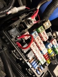
So I didn’t have to open up the fuse box I figured I would do this the easy way. First I pulled the relay and used my voltmeter on DC 10 to check the amp load (don’t want to melt 20 gauge wires or my switch). Only 290 milliamp draw so I inserted stripped wire into the two pins under the relay, loomed it and ran it through firewall and up to a switch into the map light mount. Now it works like a charm, no more jumping wire for cooldowns!
Thanks for the insights Willie!
Thanks for the insights Willie!
Attachments
Users who are viewing this thread
Total: 2 (members: 0, guests: 2)

