Fore controller issues

Status
Not open for further replies.

RBB

Well-Known Member
Established Member
Joined
Jul 3, 2013
Messages
1,354
Location
Stephens City, VA
(Note - skip to next to last paragraph if you want the short version)

I'm totally stumped on a problem I'm having with my dual pump system being run by an FC2. I'm no electrical expert, so maybe one of you guys can figure this one out. Let me start off by saying I've had this system installed for 9 months now and it's been running great, no issues to speak of. Went to start the car on Sunday and it's turning over, but not starting. Those of you with a return fuel system know how loud the pumps are, so it was easy for me to tell I had no fuel....a glance at my fuel pressure gauge confirmed.

Popped the trunk and opened up the controller, fuses are intact. Disconnected the wires for only pump 2, key on, probed the pump 2 outputs with my multimeter and I'm getting 0v, it's dead. At this point I disconnect all the controller wiring and remove it. Figured I'd start with my wiring and see if anything was up. Power lead from the battery - fuse is intact and it's hot with 12v with key on. Remote trigger wire coming from FPDM is good as well, 12v with key on. Checked my ground, rock solid, less interference back there than some of the OEM grounds in the engine bay.

At this point I check the controller out again. Nothing burned up on the circuit board, fuses are good, and no corrosion, solder, etc on any of the ports. Gave Fore a call and talked to Justin, he was stumped as well....said he'd never seen a controller go bad, but sent me a prepaid label to send it in for inspection.

Before I boxed it up this afternoon I decided to give it a more thorough testing. Went back to the trunk and hooked up power, ground, and remote only. Key on and much to my surprise both pump 1 and 2 outputs probe hot with 12V....very strange since I got nothing out of the pump 2 output when I still had pump 1 wires hooked up. At this point I figure, ok let's just hook everything back up and you should be good, it was a fluke....nope, no power to pumps. I then disconnect pump 1 wiring, key on and probe the outputs, 0v! What the hell, I'm showing both pump outputs are hot with 12v when neither of the pump wires are connected....as soon as I connect one set of wires (doesn't matter which one), both outputs are dead, confirmed 0v probed with multimeter!!

So that's it, wiring and all fuses check out, controller pump outputs probe hot with 12v with key on when neither output is connected to the pump wiring. As soon as you connect one (doesn't matter which) or both pumps then it's dead, 0v on the probe for the disconnected pump, and obviously the connected pump is not running. Even more strange, I left enough of the main power and ground wire hanging out of the controller to stick a probe on them when I reconnected everything. With only power, ground and remote wires connected, the main power wire probes 12v hot with key on. As soon as you connect either set of pump wires, that main power line coming in probes 0v with key on.

Like I said, I'm no expert with electrical work, I know the basics, but I can't figure this one out for the life of me. The system has been rock solid for 9 months and now this. Any ideas from some of you guys that are more well versed in this area?
 
Last edited:

Snoopy49

Well-Known Member
Established Member
Joined
Jun 12, 2012
Messages
6,690
Location
California
Check and make sure all the crimps on the connectors are tight and on bare wire and not the insulation. If there are in pin connectors, make sure the pins are locked in the connector housings, pull on all the wires.
 

RedVenom48

Let's go Brandon!
Established Member
Joined
Sep 29, 2014
Messages
7,973
Location
Arizona
Reply
(Note - skip to next to last paragraph if you want the short version)

I'm totally stumped on a problem I'm having with my dual pump system being run by an FC2. I'm no electrical expert, so maybe one of you guys can figure this one out. Let me start off by saying I've had this system installed for 9 months now and it's been running great, no issues to speak of. Went to start the car on Sunday and it's turning over, but not starting. Those of you with a return fuel system know how loud the pumps are, so it was easy for me to tell I had no fuel....a glance at my fuel pressure gauge confirmed.

Popped the trunk and opened up the controller, fuses are intact. Disconnected the wires for only pump 2, key on, probed the pump 2 outputs with my multimeter and I'm getting 0v, it's dead. At this point I disconnect all the controller wiring and remove it. Figured I'd start with my wiring and see if anything was up. Power lead from the battery - fuse is intact and it's hot with 12v with key on. Remote trigger wire coming from FPDM is good as well, 12v with key on. Checked my ground, rock solid, less interference back there than some of the OEM grounds in the engine bay.

At this point I check the controller out again. Nothing burned up on the circuit board, fuses are good, and no corrosion, solder, etc on any of the ports. Gave Fore a call and talked to Justin, he was stumped as well....said he'd never seen a controller go bad, but sent me a prepaid label to send it in for inspection.

Before I boxed it up this afternoon I decided to give it a more thorough testing. Went back to the trunk and hooked up power, ground, and remote only. Key on and much to my surprise both pump 1 and 2 outputs probe hot with 12V....very strange since I got nothing out of the pump 2 output when I still had pump 1 wires hooked up. At this point I figure, ok let's just hook everything back up and you should be good, it was a fluke....nope, no power to pumps. I then disconnect pump 1 wiring, key on and probe the outputs, 0v! What the hell, I'm showing both pump outputs are hot with 12v when neither of the pump wires are connected....as soon as I connect one set of wires (doesn't matter which one), both outputs are dead, confirmed 0v probed with multimeter!!

So that's it, wiring and all fuses check out, controller pump outputs probe hot with 12v with key on when neither output is connected to the pump wiring. As soon as you connect one (doesn't matter which) or both pumps then it's dead, 0v on the probe for the disconnected pump, and obviously the connected pump is not running. Even more strange, I left enough of the main power and ground wire hanging out of the controller to stick a probe on them when I reconnected everything. With only power, ground and remote wires connected, the main power wire probes 12v hot with key on. As soon as you connect either set of pump wires, that main power line coming in probes 0v with key on.

Like I said, I'm no expert with electrical work, I know the basics, but I can't figure this one out for the life of me. The system has been rock solid for 9 months and now this. Any ideas from some of you guys that are more well versed in this area?

Just to recap, when you were probing for available voltage, you had an independent ground source back to battery ground (ie body ground) and not the circuit ground?

So:

1. you had Key On Engine Off (KOEO) and had source voltage (12V) available at the main power wire to the controller.
2. you had 12v from the FPDMs to the controller as the on signal.

If Im imagining how the system is set up, it appears to be a parallel circuit at the controller that's ground side switched?

Even with the pump wires disconnected, you should still get source voltage to the power terminals if checking from the terminal to body ground with your DVOM. This is assuming of course power is supposed to be hot at all times and the pumps are ground side controlled.

From the controller to body ground is it a wire or bolted through to the body providing ground? If it was a wire, did you have less than an 1 Ohm of resistance to ground?

....hmmm

Set your DVOM to Ohms. Find the power lead to your fuel pumps and do a ground continuity check on each using a direct body ground. Should be OFL or out of range. Checking to see if your power wire from the controller to the pump is grounding somehow. If its small enough, it wont pop the fuse.

Do the same for the ground wires. It shouldnt have continuity, and if the controller is ground side switched it would run anytime the power is hot. Even still, better safe to check it now.

Next, perform a resistance check of both pumps. Should be close to zero, a few tenths of an Ohm is ok. This is a generic value, its possible that your pump manufacturer has a different spec. I just checked a repair manual for a 2001 LS430 with a return system and its fuel pump spec was .3 - 3.0 Ohms at 68F. I would imagine its about that, but check with the pump manufacturer.

If:
Your continuity to ground from the controller is ok
Your continuity to ground through the pump POWER wires are Open or OFL
Your continuity to ground through the pump GROUND wires are open or OFL
Your fuel pump resistances are within specification
You have 12V available when KOEO at the controller main to body ground, the pump 12v terminals to BODY GROUND on both pump circuits,

Id say your controller died.
 

RBB

Well-Known Member
Established Member
Joined
Jul 3, 2013
Messages
1,354
Location
Stephens City, VA
Reply

Just to recap, when you were probing for available voltage, you had an independent ground source back to battery ground (ie body ground) and not the circuit ground?

So:

1. you had Key On Engine Off (KOEO) and had source voltage (12V) available at the main power wire to the controller.
2. you had 12v from the FPDMs to the controller as the on signal.

If Im imagining how the system is set up, it appears to be a parallel circuit at the controller that's ground side switched?

Even with the pump wires disconnected, you should still get source voltage to the power terminals if checking from the terminal to body ground with your DVOM. This is assuming of course power is supposed to be hot at all times and the pumps are ground side controlled.

From the controller to body ground is it a wire or bolted through to the body providing ground? If it was a wire, did you have less than an 1 Ohm of resistance to ground?

....hmmm

Set your DVOM to Ohms. Find the power lead to your fuel pumps and do a ground continuity check on each using a direct body ground. Should be OFL or out of range. Checking to see if your power wire from the controller to the pump is grounding somehow. If its small enough, it wont pop the fuse.

Do the same for the ground wires. It shouldnt have continuity, and if the controller is ground side switched it would run anytime the power is hot. Even still, better safe to check it now.

Next, perform a resistance check of both pumps. Should be close to zero, a few tenths of an Ohm is ok. This is a generic value, its possible that your pump manufacturer has a different spec. I just checked a repair manual for a 2001 LS430 with a return system and its fuel pump spec was .3 - 3.0 Ohms at 68F. I would imagine its about that, but check with the pump manufacturer.

If:
Your continuity to ground from the controller is ok
Your continuity to ground through the pump POWER wires are Open or OFL
Your continuity to ground through the pump GROUND wires are open or OFL
Your fuel pump resistances are within specification
You have 12V available when KOEO at the controller main to body ground, the pump 12v terminals to BODY GROUND on both pump circuits,

Id say your controller died.
That's right, I was using an independent ground source when probing for voltage and the system is a parallel circuit at the controller that's ground side switched. There's a short length of 6 gauge wire running from the controller that's bolted directly to the body providing ground. Resistance on that is .5 Ohm.

I'll check the pump wires for continuity tonight. How would you check the pumps themselves for resistance?

Thanks for the post, Ed. What's throwing me off about the whole situation is when I just hook up power, remote trigger, and ground to the controller I can probe both sets of pump outputs and they read hot with 12V. If I hook up either set (or both) of the pump wires to the controller then the outputs are suddenly dead. The open pump ports read 0V....I can't stick a probe in the wired pump port at that point, but it's obviously dead as well since one pump isn't running.
 
Last edited:

RedVenom48

Let's go Brandon!
Established Member
Joined
Sep 29, 2014
Messages
7,973
Location
Arizona
For the pumps themselves, you'd stick your leads into each terminal of the pump being tested. Idea is to "complete" the circuit for that pump. The DVOM will send a very small electrical current through the circuit via the red lead, read what its getting back from the black lead and interpret that as a resistance in Ohms. There should be a specific Ohm spec, Id give the pump manufacturer a call and see what they give you.

Ground wire resistance is ok at .5 Ohms

My best guess is there is something internal to the controller that's gone belly up. When things like this fail, they can often to weird stuff, especially with this looking like its a solid state controller.

Id just verify that all connections to the FC2 are tight and do your resistance and continuity checks and if they are good, controller failed.
 

RBB

Well-Known Member
Established Member
Joined
Jul 3, 2013
Messages
1,354
Location
Stephens City, VA
For the pumps themselves, you'd stick your leads into each terminal of the pump being tested. Idea is to "complete" the circuit for that pump. The DVOM will send a very small electrical current through the circuit via the red lead, read what its getting back from the black lead and interpret that as a resistance in Ohms. There should be a specific Ohm spec, Id give the pump manufacturer a call and see what they give you.

Ground wire resistance is ok at .5 Ohms

My best guess is there is something internal to the controller that's gone belly up. When things like this fail, they can often to weird stuff, especially with this looking like its a solid state controller.

Id just verify that all connections to the FC2 are tight and do your resistance and continuity checks and if they are good, controller failed.
I'll perform the remaining checks you're recommending tonight, thanks man. I'd have to think it's a controller issue as well, which is odd because Justin tells me they've never had one fail before. I did pull the back seat and all the wiring at the hat was fine. Pumps are plugged in, connectors are fully seated, and none of the pins in the connectors have come out, all the wiring there is tight. What are the odds that both fuel pumps would fail at exactly the same time? That's highly unlikely, and I know that the pumps aren't getting any voltage once I plug any pump leads into the controller anyways.
 

Catmonkey

I Void Warranties!
Established Member
Premium Member
Joined
May 20, 2011
Messages
3,854
Location
Louisiana
I have no clue, but I'd be interested to hear what you find to be the problem.
 

RBB

Well-Known Member
Established Member
Joined
Jul 3, 2013
Messages
1,354
Location
Stephens City, VA
For the pumps themselves, you'd stick your leads into each terminal of the pump being tested. Idea is to "complete" the circuit for that pump. The DVOM will send a very small electrical current through the circuit via the red lead, read what its getting back from the black lead and interpret that as a resistance in Ohms. There should be a specific Ohm spec, Id give the pump manufacturer a call and see what they give you.

Ground wire resistance is ok at .5 Ohms

My best guess is there is something internal to the controller that's gone belly up. When things like this fail, they can often to weird stuff, especially with this looking like its a solid state controller.

Id just verify that all connections to the FC2 are tight and do your resistance and continuity checks and if they are good, controller failed.
All wiring/pumps checked out ok tonight. It’s either the controller or one thing I just thought of is my fuse holder. It’s an AGU style (glass) fuse and just found quite a few threads on the web talking about partial failures with these types of fuses.

The middle of the fuse will look fine, so visually it checks out, but the solder where the blade is connected to the metal end caps heats up and comes loose. Apparently they will still pass voltage through when this happens, but not enough current to operate your components. This is right in line with what I’m experiencing so I’m going to pick up a mini ANL fuse holder tomorrow and swap that out. Hoping it’s as simple as that.
 
Last edited:

RedVenom48

Let's go Brandon!
Established Member
Joined
Sep 29, 2014
Messages
7,973
Location
Arizona
All wiring/pumps checked out ok tonight. It’s either the controller or one thing I just thought of is my fuse holder. It’s an AGU style (glass) fuse and just found quite a few threads on the web talking about partial failures with these types of fuses.

The middle of the fuse will look fine, so visually it checks out, but the solder where the blade is connected to the metal end caps comes loose. Apparently they will still pass voltage through when this happens, but not enough current to operate your components. This is right in line with what I’m experiencing so I’m going to pick up a mini ANL fuse holder tomorrow and swap that out. Hoping it’s as simple as that.
Is this fuse type one thats included with the Fore wiring, or do you have to provide that for yourself?

Good point about the voltage check. The amount of current that controller is capable of will usually far exceed what a DVOM can typically handle. Popped DVOM fuse city right there.

Did you already send the controller back?
 

RBB

Well-Known Member
Established Member
Joined
Jul 3, 2013
Messages
1,354
Location
Stephens City, VA
Is this fuse type one thats included with the Fore wiring, or do you have to provide that for yourself?

Good point about the voltage check. The amount of current that controller is capable of will usually far exceed what a DVOM can typically handle. Popped DVOM fuse city right there.

Did you already send the controller back?
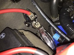
The Fore kit actually came with a mini ANL style fuse and holder. Unfortunately mine melted down a couple of months ago. The fuse was fine, pumps were still running, but obviously the holder needed to be replaced. Couldn't find an explanation for it....the set screws were still tight, connections weren't loose....don't know why it heated up like that. I was trying to get back up and running the next day to hit the track and all I had available locally was the AGU fuse holder so I used it.

IMG_0358.JPG

I didn't send the controller back yet, wanted to exhaust all my options before doing that. I'll replace the fuse holder with a blade type again this weekend and see if that does the trick. Knowing my luck, I've spent hours testing everything and that will be the issue.
 
Last edited:

RBB

Well-Known Member
Established Member
Joined
Jul 3, 2013
Messages
1,354
Location
Stephens City, VA
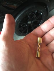
Ended up being the fuse. I guess the solder on one of the end caps came loose, causing it to be unable to pass the required current. Wasted a lot of time over that thing this week.

Note to self, never use an AGU fuse again. You absolutely cannot visually tell there’s anything wrong with these things when they fail like that. It was even passing the continuity check on a multimeter.

EEC43ABD-831B-4FE0-98A4-E7FF0586CA29.jpeg
 

RedVenom48

Let's go Brandon!
Established Member
Joined
Sep 29, 2014
Messages
7,973
Location
Arizona
Wow what a gremlin! Id be suuuper pissed. Haha, how big is the hammer going to be when you start smashing? Glad its resolved Russ
 

DSG2003Mach1

Well-Known Member
Established Member
Premium Member
Joined
Apr 15, 2004
Messages
16,019
Location
Central Fl
Ended up being the fuse. I guess the solder on one of the end caps came loose, causing it to be unable to pass the required current. Wasted a lot of time over that thing this week.

Note to self, never use an AGU fuse again. You absolutely cannot visually tell there’s anything wrong with these things when they fail like that. It was even passing the continuity check on a multimeter.

View attachment 1514336

Damn, that would have driven me crazy. I think the only fuse I have like that is for my stereo so not terribly concerned but good to keep in mind
 

RBB

Well-Known Member
Established Member
Joined
Jul 3, 2013
Messages
1,354
Location
Stephens City, VA
Wow what a gremlin! Id be suuuper pissed. Haha, how big is the hammer going to be when you start smashing? Glad its resolved Russ
Pretty big hammer. I did smash it open to see if I could find the point of failure. Nothing really looked out of the ordinary.
Damn, that would have driven me crazy. I think the only fuse I have like that is for my stereo so not terribly concerned but good to keep in mind
Well at least you know what to check first if your stereo stops working. Even if the fuse looks good, replace that first.
 

blowbye

Bangin gears
Established Member
Joined
Oct 4, 2006
Messages
379
Location
USA
I had a problem with my fc3 controller. It worked intermittently. If i went the the controller and knock on it it would fire up. The pumps would turn on but when i went to start the car they would not continue to run untill i knocked (hit) the controller. I tinned all my wires and every connection looked great. But when i opened up the controller i noticed that a very little bit of the plastic had melted on the back side of the terminal that was causing it to shut off. Cleaned up the plastic with a hobby knife and sprayed everything with contact cleaner. And tightend the set screws down. I check them every month or so. If you melted your fuse you may have melted the inside terminal as well. Dont know if this help but figured I would let you know.
 
Status
Not open for further replies.

Users who are viewing this thread


Top