Cobra Engineering Head Cooling Mod Install using -12AN
This was the best way I was able to find readily available connectors to do this. Certain adapters such as 90° 3/8 NPT to -12 are really expensive so it is much cheaper to step it up using -10/-12 adapters. You could really get away with -10 on this but -12 matches up to the 3/4 heater hose coming from the heater core.
Feel free to comment with the adapters/parts lists that you used to complete your kit, there are many different ways to accomplish this, this is just how I made the kit to work well with my car so I thought I would share. The quality on the Cobra Engineering kit is second to none and allows alot of flexibility.
First you will need to purchase the Cobra Engineering Head Cooling mod from Cobra Engineering LLC
Parts that I used (Part #’s from Summit Racing):
2x AER-FBM1015 FITTING #12 STRAIGHT
1x FRA-498306 T FEM SWIVEL ON RUN
2x MRG-A3810B 3/8 NPT TO -10AN 90 DEGREES
1x SUM-220224 -10 TO -12 ADAPTER
1x SUM-230203 S.S. HOSE -12 3FT
1x RUS-640571 ADAPTER FITTING
1x RUS-670330-12 BARB FITTING
Parts from hardware store:
1x Metric 8mm button head allen bolt to clear the hose/adapter fitting, not sure of the pitch (I think this was 8mm I did not write the size down so someone correct me if I am wrong on the size).
My total cost was ~$260
To Install:
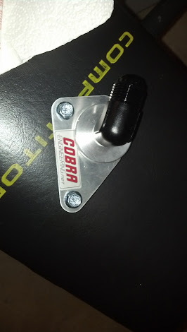
First Install the 90° 3/8 NPT adapters into the Cobra Engineering adapters, use some thread sealer since these are pipe threads (this is all the thread sealer that you should need since the remaining connections are using AN fittings that do not require sealer.
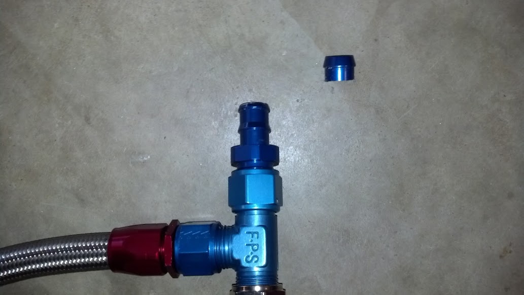
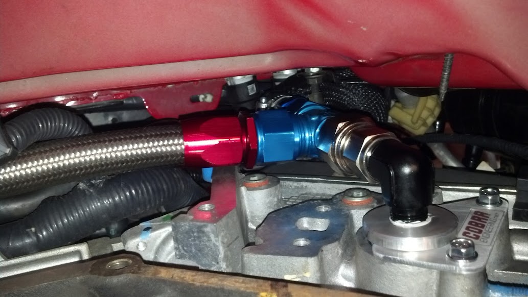
Next loosely connect the -10 to -12 adapter to the driver’s side 90° elbow, then connect a -12 hose end (take the collar off of the hose end so that you can see the nipple that the -12 hose slides onto)
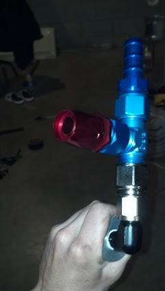
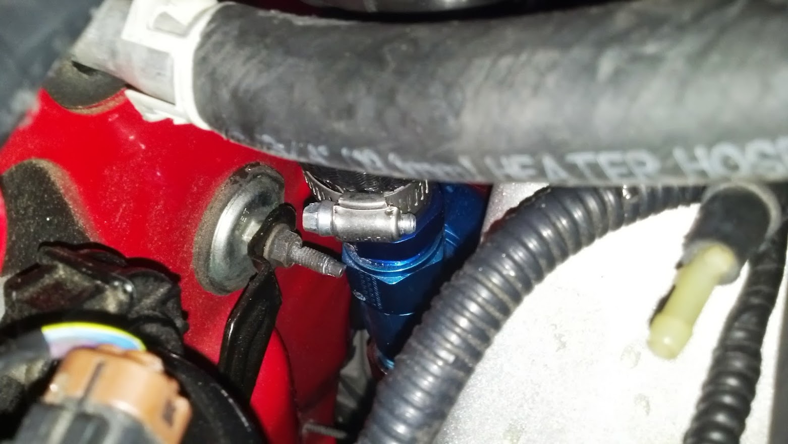
Now loosely assemble the passenger side, after the 90° elbow install the -10 to -12 female to female adapter, then the -12 tee fitting with the female end on top, and on the very top screw in the ¾ nipple. Once again put a -12 hose end on the left side of the tee fitting (take the collar off of the hose end so that you can see the nipple that the -12 hose slides onto).
Place both assemblies into the heads and measure from nipple to nipple to figure out what length to cut the -12 hose (better to measure too long then too short, since these ends can be disassembled and the hose recut).
Next you will need to figure out how much to cut from the hose leading to the heater core (I removed the hose, it was much easier this way, you will probably find it easier to never engage the heater hose back onto the heater core completely until you are ready to install it back it for good since it can be a pain to get loose). On my install it was necessary to remove the restrictor in order to allow the nipple to fully engage the hose properly. To remove the restrictor cut the band clamp on the hose and get a really long lag screw and screw it into the reducer and give it a pull to remove it from the hose.
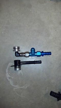
In order to get my hose geometry correct, I ended up taking about 2 inches off the hose, I also took the first part of the nipple off of the ¾ hose barb to reduce the pressure on the bend of the heater hose. See below for a comparison of the height of the stock piece vs the replacement passenger side piece. The main thing here is to make sure that the bend in the factory hose is not too extreme or bunches up at the top because enough length was not cut off.
Once the heater hose is cut test fit everything together, the tee fitting will need to be tightened at a slight angle to clear the head/block, on the driver’s side the upper bolt will need to be replaced with the button cap allen head bolt so the hose will clear.
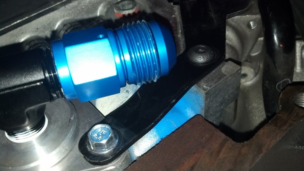
I would also trim the bolt pictured below even with the nut. (On my car I left it originally because it cleared but when the engine moved around the stud began to rub the AN fittings after around 250 miles, it would be better to take care of the bolt before it becomes a problem because it is tighter to get to after the fact)
Once the fit is verified, take the parts back off (you might not have to remove the heater hose, but it does make it easier to attach the heater hose to the tee fitting while off of the car). Assemble the parts outside of the car as an assembly. Put dielectric grease or antifreeze on the O-rings an install the assembly into the cylinder heads and attach the heater hose connector to the heater core. Then pressure test and refill/burp the system.


:beer:
This was the best way I was able to find readily available connectors to do this. Certain adapters such as 90° 3/8 NPT to -12 are really expensive so it is much cheaper to step it up using -10/-12 adapters. You could really get away with -10 on this but -12 matches up to the 3/4 heater hose coming from the heater core.
Feel free to comment with the adapters/parts lists that you used to complete your kit, there are many different ways to accomplish this, this is just how I made the kit to work well with my car so I thought I would share. The quality on the Cobra Engineering kit is second to none and allows alot of flexibility.
First you will need to purchase the Cobra Engineering Head Cooling mod from Cobra Engineering LLC
Parts that I used (Part #’s from Summit Racing):
2x AER-FBM1015 FITTING #12 STRAIGHT
1x FRA-498306 T FEM SWIVEL ON RUN
2x MRG-A3810B 3/8 NPT TO -10AN 90 DEGREES
1x SUM-220224 -10 TO -12 ADAPTER
1x SUM-230203 S.S. HOSE -12 3FT
1x RUS-640571 ADAPTER FITTING
1x RUS-670330-12 BARB FITTING
Parts from hardware store:
1x Metric 8mm button head allen bolt to clear the hose/adapter fitting, not sure of the pitch (I think this was 8mm I did not write the size down so someone correct me if I am wrong on the size).
My total cost was ~$260
To Install:
First Install the 90° 3/8 NPT adapters into the Cobra Engineering adapters, use some thread sealer since these are pipe threads (this is all the thread sealer that you should need since the remaining connections are using AN fittings that do not require sealer.
Next loosely connect the -10 to -12 adapter to the driver’s side 90° elbow, then connect a -12 hose end (take the collar off of the hose end so that you can see the nipple that the -12 hose slides onto)
Now loosely assemble the passenger side, after the 90° elbow install the -10 to -12 female to female adapter, then the -12 tee fitting with the female end on top, and on the very top screw in the ¾ nipple. Once again put a -12 hose end on the left side of the tee fitting (take the collar off of the hose end so that you can see the nipple that the -12 hose slides onto).
Place both assemblies into the heads and measure from nipple to nipple to figure out what length to cut the -12 hose (better to measure too long then too short, since these ends can be disassembled and the hose recut).
Next you will need to figure out how much to cut from the hose leading to the heater core (I removed the hose, it was much easier this way, you will probably find it easier to never engage the heater hose back onto the heater core completely until you are ready to install it back it for good since it can be a pain to get loose). On my install it was necessary to remove the restrictor in order to allow the nipple to fully engage the hose properly. To remove the restrictor cut the band clamp on the hose and get a really long lag screw and screw it into the reducer and give it a pull to remove it from the hose.
In order to get my hose geometry correct, I ended up taking about 2 inches off the hose, I also took the first part of the nipple off of the ¾ hose barb to reduce the pressure on the bend of the heater hose. See below for a comparison of the height of the stock piece vs the replacement passenger side piece. The main thing here is to make sure that the bend in the factory hose is not too extreme or bunches up at the top because enough length was not cut off.
Once the heater hose is cut test fit everything together, the tee fitting will need to be tightened at a slight angle to clear the head/block, on the driver’s side the upper bolt will need to be replaced with the button cap allen head bolt so the hose will clear.
I would also trim the bolt pictured below even with the nut. (On my car I left it originally because it cleared but when the engine moved around the stud began to rub the AN fittings after around 250 miles, it would be better to take care of the bolt before it becomes a problem because it is tighter to get to after the fact)
Once the fit is verified, take the parts back off (you might not have to remove the heater hose, but it does make it easier to attach the heater hose to the tee fitting while off of the car). Assemble the parts outside of the car as an assembly. Put dielectric grease or antifreeze on the O-rings an install the assembly into the cylinder heads and attach the heater hose connector to the heater core. Then pressure test and refill/burp the system.
:beer:
Last edited:

