Looking for vacuum line photos

kreymis

Member
Established Member
Joined
May 4, 2012
Messages
78
Location
croton, ny
Thanks Vinnie. I really appreciate the help. I wish New York was looser on the emissions nonsense


Sent from my iPhone using svtperformance.com
 

Vinnie_B

"LIVE LIFE AT FULL THROTTLE"
Established Member
Premium Member
Joined
Jun 22, 2021
Messages
1,973
Location
Michigan
I’ve done all of this multiple times. Have now put over 400 miles on the car. All different driving conditions. Followed the specific conditions for egr and cat to set and no change. I’m at the point of just throwing parts at the car now.


Sent from my iPhone using svtperformance.com
Ok. I'll take a look at why these monitors are not accessible. More than likely it's a com or electrical issue. I report back when I can!!
 

Vinnie_B

"LIVE LIFE AT FULL THROTTLE"
Established Member
Premium Member
Joined
Jun 22, 2021
Messages
1,973
Location
Michigan
I’ve done all of this multiple times. Have now put over 400 miles on the car. All different driving conditions. Followed the specific conditions for egr and cat to set and no change. I’m at the point of just throwing parts at the car now.


Sent from my iPhone using svtperformance.com
Have you tried this yet @kreymis


Clear The Continuous Diagnostic Trouble Codes (DTCs) And Reset The Emission Monitors Information in The Powertrain Control Module (PCM)​

Description
Note:
Clear the continuous diagnostic trouble codes (DTCs) and reset the emission monitors information in the powertrain control module (PCM) was previously called PCM reset.
All OBD scan tools support the clearing of continuous DTCs and resetting of emission monitors information in the PCM.
The clearing of the continuous DTCs allows the scan tool to command the PCM to clear/reset all emission-related diagnostic information. While carrying out this operation a DTC P1000 will be stored in the PCM until all the OBD system monitors or components have been tested to satisfy a drive cycle without any other faults occurring.


The following events occur when the continuous DTCs and emission monitors information is cleared from the PCM:
  • Clears the number of DTCs.
  • Clears the DTCs.
  • Clears the freeze frame data.
  • Clears the diagnostic monitoring test results.
  • Resets the status of the OBD system monitors.
  • Sets DTC P1000.

If this dont help I suspect an issue could possible be here that is not allowing certain emissions data to be collected

Comprehensive Component Monitor​

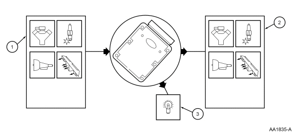
The Comprehensive Component Monitor (CCM) monitors for malfunctions in any powertrain electronic component or circuit that provides input or output signals to the PCM that can affect emissions and is not monitored by another OBD II monitor. Inputs and outputs are, at a minimum, monitored for circuit continuity or proper range of values. Where feasible, inputs are also checked for rationality, outputs are also checked for proper functionality.

CCM covers many components and circuits and tests them in various ways depending on the hardware, function, and type of signal. For example, analog inputs such as Throttle Position or Engine Coolant Temperature are typically checked for opens, shorts and out-of-range values. This type of monitoring is performed continuously. Some digital inputs like Vehicle Speed or Crankshaft Position rely on rationality checks - checking to see if the input value makes sense at the current engine operating conditions. These types of tests may require monitoring several components and can only be performed under appropriate test conditions.

Outputs such as the Idle Air Control solenoid are checked for opens and shorts by monitoring a feedback circuit or "smart driver" associated with the output. Other outputs, such as relays, require additional feedback circuits to monitor the secondary side of the relay. Some outputs are also monitored for proper function by observing the reaction of the control system to a given change in the output command. An Idle Air Control solenoid can be functionally tested by monitoring idle rpm relative to the target idle rpm. Some tests can only be performed under appropriate test conditions; for example, transmission shift solenoids can only be tested when the PCM commands a shift.

The following is an example of some of the input and output components monitored by the CCM. The components monitor may belong to the engine, ignition, transmissions, air conditioning, or any other PCM supported subsystem.

  1. Inputs:

    mass air flow (MAF) sensor, intake air temperature (IAT) sensor, engine coolant temperature (ECT) sensor, throttle position (TP) sensor, camshaft position (CMP) sensor, air conditioning pressure sensor (ACPS), fuel tank pressure (FTP) sensor.
  2. Outputs:

    fuel pump (FP), wide open throttle A/C cutout (WAC), idle air control (IAC), shift solenoid (SS), torque converter clutch (TCC) solenoid, intake manifold runner control (IMRC), EVAP canister purge valve, canister vent (CV) solenoid.
  3. CCM is enabled after the engine starts and is running. A Diagnostic Trouble Code (DTC) is stored in keep alive memory and the MIL is illuminated after two driving cycles when a malfunction is detected. Many of the CCM tests are also performed during on demand self-test.

    imagen2.dll

    Comprehensive Component Monitor


More Info that might be of some use to you:


Readiness Monitors Overview​

The purpose of readiness monitors in a car is to self-test the car’s emission systems. Readiness monitors are self check routines that observe the performance of specific vehicle emissions control systems. Cars may perform up to 11 system tests; these are so called readiness monitors. The output of readiness monitors identifies whether the car’s computer has completed the required tests while the car is being driven.

There are two different types of monitors: continuous and non-continuous. Continuous monitors are different in design from the non-continuous monitors. Continuous monitors are being constantly tested and evaluated by the car’s computer while the car is running. Conversely, the non-continuous monitors require certain conditions to be met before a test or series of tests can be completed. The conditions necessary for the car to run these self-diagnostic tests vary. Some monitors require that the car follows a predefined “drive cycle” routine. Some require two drive cycles due to the need for cool down and warm up periods in between.

The OBD system monitors some functions every time you drive your vehicle, but only checks other functions under certain driving or operating conditions. Some checks are “continuous” and are ongoing all the time


OBD II Readiness Monitors​


Continuous Monitors​


Comprehensive Component Monitor​

The PCM executes the comprehensive component monitor whenever the engine is in operation. The monitor tests for concerns in any powertrain electronic component or circuit that provides input or output signals to the PCM that can affect emissions and is not monitored by another on board diagnostics (OBD) monitor. Inputs and outputs are, at a minimum, monitored for circuit continuity or correct range of values. Where feasible, inputs are also checked for rationality, and outputs are also checked for correct functionality.

Comprehensive component monitoring covers many components and circuits and tests them in various ways depending on function and type of signal. For example, analog inputs such as throttle position or engine coolant temperature are typically checked for opens, shorts, and out-of-range values. Some digital inputs like brake switch or crankshaft position rely on rationality checks - checking to see if the input value makes sense at the current engine operating conditions.

Outputs such as coil drivers are checked for opens and shorts by monitoring a feedback circuit or smart driver associated with the output. Some outputs are also monitored for correct function by observing the reaction of the control system to a given change in the output command. An idle air control solenoid can be functionally tested by monitoring the idle RPM relative to the target idle RPM. Some tests can only be carried out under the appropriate test conditions. For example, the transmission shift solenoids can only be tested when the PCM commands a shift.


Non-Continuous Monitors​

Other OBD II monitors are only active during certain times. These are the "non-continuous" monitors and include the catalytic converter efficiency monitor, the evaporative system monitor that detects fuel vapor leaks in the fuel system, the EGR system monitors, the secondary air system monitor (if the vehicle has such a system), and the oxygen sensor monitors.


Non-Continuous Monitors​


Oxygen (O2) Sensor​

The oxygen sensor monitor allows the PCM to verify that the O2 sensors are properly calibrated and functioning without noticeable deterioration under normal engine operating conditions. This ensures that when the PCM is controlling fuel mixture during closed-loop operation, an actual air/fuel ratio of 14.7:1 is being combusted in the cylinders. When the air/fuel ratio moves away from this ideal point catalytic converter efficiency decreases and emissions increase.

The PCM enables the oxygen sensor monitor after the engine and catalytic converter have been brought up to normal operating temperature, to reach closed loop operation, and the vehicle is maintaining a steady speed above 25 mph for several minutes. For the monitor to run, the check engine light needs to be commanded off by the PCM and the continuous monitors must have completed successfully.

The PCM tests all the oxygen sensors when the monitor is enabled. The upstream O2 sensors are checked for proper voltage threshold and response rate to air/fuel mixture changes (switching from rich to lean). The downstream O2 sensors are checked for proper voltage threshold and the ability to recognize lean conditions. Both sensors are monitored for signal rationality.

While the monitor is running, the PCM executes a fixed frequency fuel control routine and observes the upstream sensors’ output voltage and switching response frequency. The PCM also shuts off the fuel injectors during a period of deceleration and observes the downstream sensors’ voltage response to the lean condition.

The check engine light is illuminated by the PCM when an oxygen sensor fault has been detected after 2 drive cycles.


Non-Continuous Monitors​


Oxygen Sensor Heater Monitor​

OBD II equipped vehicles use heated oxygen sensors. Heated oxygen sensors have an internal heater circuit that brings the sensor up to operating temperature more quickly than an unheated sensor. The heater will bring the sensor up to operating temperature within 20 to 60 seconds depending on the sensor, and also keep the oxygen sensor hot even when the engine is idling for a long period of time. The faster the oxygen sensor heats up, the quicker the PCM can enter closed loop fuel control, optimizing catalytic converter efficiency.

On most OBD II systems the oxygen sensor heater monitor runs concurrently with the oxygen sensor monitor or continuously when the engine is running. However, the successful completion of the monitors are independent events. Typically the PCM will enable the monitor, conditions for completing the oxygen sensor monitor will be met and that monitor will successfully complete. Some enabling criteria to complete the oxygen sensor heater monitor may not always occur and the heater monitor goes uncompleted for several drive cycles. This may happen more frequently as the sensors age and the sensors’ heating element deteriorates.

During oxygen sensor heater monitoring the PCM turns the heater strip circuit on and off for each sensor and looks for an expected change in current. On some OBD II systems the PCM continuously monitors current flow through the heater circuit. The heater circuit of each oxygen sensor is evaluated independently.


Non-Continuous Monitors​


Catalytic Converter Monitor​

The catalytic converter monitor evaluates the ability of the converter to reduce harmful emissions. When the catalyst in the converter is working correctly, oxygen from the exhaust gas is used up in the breakdown of other components (pollutants) of the exhaust gas. Under normal closed loop fuel control operating conditions, all the oxygen entering the converter is used up in the reaction. The PCM measures the level of oxygen entering and leaving the converter and calculates converter efficiency. This is accomplished by comparing the outputs from the upstream and downstream oxygen sensors. If the converter is functioning, there should be little unburned oxygen left in the exhaust as it exits the converter.

During closed loop fuel control, pulses of oxygen from each cylinder’s combustion event hits the upstream oxygen sensor in very rapid succession. The resultant voltage signal produced by the oxygen sensor oscillates with the oxygen pulses. At the outlet of the catalytic converter, the downstream oxygen sensor measures no oxygen and its signal is a constant voltage indicating all the oxygen has been used up. If the downstream oxygen sensor reading is fluctuating from high to low similar to the front sensor, it means the converter is not functioning. The PCM will illuminate the check engine light if the difference in oxygen sensor signals indicates a drop in converter efficiency has happened that may allow emissions to increase to a level that is 1.5 times the federal certification limit.

In order for the PCM to enable the catalytic converter monitor the check engine light has to be commanded off, continuous monitors and in most cases, the oxygen sensor monitor must have been successfully completed. The PCM can begin the monitor when the engine is operating under normal operating conditions at steady highway speeds. The PCM adds extra fuel into the catalytic converter through the fuel injectors to get the internal temperature up to proper testing temperatures of over 1000 degrees Fahrenheit. The PCM observes and compares the upstream and downstream oxygen sensor signals.

The PCM will successfully complete the catalytic converter monitor if the efficiency of the converter is calculated to be above 50%. The PCM will set a pending code if the efficiency of the converter is calculated to be below 50%. The PCM will command the check engine light to illuminate and store a DTC if the fault occurs during 2 drive cycles.


Non-Continuous Monitors​


EGR System Monitor​

Not all OBD II equipped engines have an EGR valve or EGR system; on those systems this monitor is not used. The EGR system monitor allows the PCM to test the function and the exhaust gas flow through the EGR system. The monitor is activated during EGR system operation that occurs under normal engine and vehicle operating conditions. As with most other monitored OBD II systems, all EGR electrical components are checked for electrical and rationality faults during continuous monitoring.

On OBD II equipped vehicles two main strategies are used to test the EGR system. One strategy uses a temperature sensor to measure exhaust flow through the EGR system when the EGR valve is commanded on by the PCM. With this strategy the temperature sensor signal can also identify EGR flow at times it is not wanted such as during engine idling.

The other strategy used to test the EGR system uses an EGR valve sensor to measure EGR valve position which then infers EGR flow through changes in manifold pressure occurring when the PCM commands EGR flow.

The EGR monitor is performed during driving. The PCM enables the flow rate test of the EGR system monitor after the vehicle is maintaining a steady speed above 25 mph and the EGR valve is commanded on. For the monitor to run, the check engine light needs to be commanded off by the PCM and the continuous monitors must have completed successfully.

The PCM will successfully complete the EGR monitor if the proper flow of EGR is detected and no EGR flow at idle is indicated. If the flow rate detected is too low or too high or present at idle the PCM will set a pending code. The PCM will command the check engine light to illuminate and store a DTC if the fault occurs during 2 drive cycles.


Non-Continuous Monitors​


EVAP System Monitor​

The EVAP system monitor allows the PCM to test the integrity of the fuel system and its ability to draw fuel vapor into the engine for combustion. A portion of the monitor is activated during canister purge operation that occurs under normal engine and vehicle operating conditions. The leak detection portion of the monitor may be activated under normal engine and vehicle operating conditions, during extended idle or soon after the vehicle has been shut off. As with most other monitored OBD II systems, all EVAP electrical components are checked for electrical and rationality faults during continuous monitoring.

The EVAP system monitor checks for fuel vapor leaks by performing either a pressure or vacuum test on the fuel system. For 1996 through 1999 vehicles, the federal standard allows leaks up to the equivalent of a hole .040 inches in diameter in a fuel vapor hose or filler cap. For 2000 and newer vehicles, the leakage rate has been reduced to the equivalent of a .020 in. diameter hole. The EVAP monitor checks for fuel vapor leaks (including a loose or missing gas cap).

During EVAP system monitoring the PCM tests for vapor leaks by applying vacuum or pressure to the fuel tank, vapor lines and charcoal canister. If the PCM detects no airflow when the EVAP canister purge valve is opened, or it detects a leak that equals or exceeds the amount of air that would pass through a hole 0.040 inches in diameter (0.020 inches for 2000 and up model year vehicles) a pending DTC fault code is stored. The PCM will command the check engine light to illuminate and store a DTC if the fault occurs during 2 drive cycles.

The requirements for running the EVAP monitor vary depending on the year, make and model of your vehicle. Generally speaking, the fuel tank must be 1/4 to 3/4 full because a near empty tank or a full tank can affect the accuracy of the EVAP self-test. The ambient outside temperature must not be too hot (above 95 degrees) or too cold (below 30 degrees) because this affects fuel volatility and the amount of vapor inside the tank. The vehicle must also have sat overnight or for at least 8 hours without being driven. On some vehicles, the EVAP monitor runs when the vehicle has been cruising on the highway at light throttle at a speed of 45 to 65 mph for at least 10 minutes or more. All of the components in the EVAP control system must also be functioning normally. The presence of any EVAP related DTC fault codes will prevent the EVAP System monitor from running.


OBD Drive Cycles​


Universal Drive Cycle​

In order for the PCM to properly execute all the readiness monitors on a particular vehicle, an OBD II drive cycle needs to be driven to achieve the enabling conditions for each monitor. The correct drive cycle for your vehicle can vary greatly depending on the vehicle’s year, make, model and manufacturer. The type of monitor you are trying to execute can also dictate the type of driving you need to perform.

Vehicle specific drive cycle information can be found in the manufacturer’s service information, aftermarket service information, various websites and may also be included in the vehicle owner’s manual. Typically, a few days of normal driving, both city and highway, will make the monitors ready. The following generic drive cycle can be used as a guideline if a specific drive cycle is not known. It will assist with resetting monitors when a car specific drive cycle is not available. However, it may not work for all vehicles and readiness monitors.

  • The universal OBD-II drive cycle begins with a cold start (coolant temperature below 122 F, and the coolant and air
    temperature sensors within 11 degrees of one another). This condition is easily achieved by letting the car sit overnight.
  • The ignition key must not be left on prior to the cold start. Otherwise the heated oxygen sensor diagnostic may not run.
  • Start the engine and idle the engine in drive for two and half minutes, with the A/C and rear defroster on if equipped.
  • Turn the A/C and rear defroster off, and accelerate to 55 mph under moderate, constant acceleration. Hold at a steady
    speed for three minutes.
  • Decelerate (coast down) to 20 mph without braking or depressing the clutch for manual transmissions.
  • Accelerate back to 55-60 mph at 3/4 throttle. Hold at a steady speed for five minutes.
  • Decelerate (coast down) to a stop without braking


Monitor Status​


Monitor Status: Ready VS Not Ready​

OBD II equipped vehicles follow standardized protocols when reporting monitor status to scan tools or emissions inspection device equipment. When a particular monitor is not applicable to the vehicle being tested, the monitor is reported as unsupported. The vehicle cannot report the results of this monitor simply because it does not exist. Most gasoline-powered OBD II vehicles have at least a few unsupported monitors. Unsupported monitors have no role in the overall readiness evaluation or the overall OBD inspection result.

Those monitors incorporated into the vehicle manufacturer’s emissions control design are referred to as being supported. Supported monitors need to be evaluated by the vehicle’s PCM during readiness monitoring. For most gasoline powered light duty vehicles, the common range of the number of supported monitors is six to eight. When the PCM successfully completes the execution of a particular monitor, the readiness system status will be reported as Ready or Complete. Once a monitor is set as Ready or Complete it will remain in this state unless diagnostic trouble codes (DTCs) are cleared by a scan tool or if the PCM’s short term memory is erased by a power failure (i.e., disconnecting the battery). Since the three continuous monitors are constantly evaluating, they will be reported as Ready all of the time. If testing of a particular supported non-continuous monitor has not been completed, the monitor status will be reported as Not Complete or Not Ready.

Just because the monitor status for a particular readiness monitor is Ready or Complete, this does not mean the PCM stops executing the monitor. Whenever the enabling conditions for a particular monitor are met, the PCM runs the monitor. If the monitor runs successfully or is interrupted nothing is changed by the PCM. But if a monitor executes and a fault is incurred, a pending code is typically set in memory. And if the fault continues to happen, the PCM illuminates the check engine light and DTC fault code is set.

In most cases to turn the check engine light off and reset the monitor status to Ready, the vehicle has to be repaired and the monitor needs to be run again.


Any of the following may cause your vehicle to not be ready:

Disconnecting the battery for any reason. This erases the memory in the PCM, including stored fault codes and previous OBD monitor test results. It's like resetting the clock back to zero. Consequently, it may take several days (or even weeks) of driving before all of the monitors will run, allowing your vehicle to be tested.

Erasing stored codes with a scan tool. This also resets all of the monitors back to zero, so allow plenty of time for the monitors to run before driving back to the emissions test facility. If any of the erased fault codes reappear, it may prevent one or more of the monitors from completing.

Disconnecting sensors. This will prevent the monitors from running and will likely set one or more fault codes. Removing the catalyst converter. This is emissions tampering and is illegal for street-driven vehicles.


Monitor Status​


Helping set Monitors​

First, make sure that the check engine light is not commanded on. Having stored DTC faults or even pending diagnostic trouble codes active may prevent a monitor from running to completion.

Second, make sure that you have enough fuel in the car. Some monitors, for instance the EVAP monitor, may require the fuel level to be between 35% and 85% to enable the monitor to execute.

Third, complete the drive cycle.

EVAP Drive Cycles
The following are sample drive cycles for the EVAP monitor:

Ford: With fuel tank one half to three-quarters full, cruise at 45 to 65 mph for 10 minutes. Avoid sharp turns and hills during this period.

An example of some common enabling criteria to run the EVAP monitors drive cycle:

  • The malfunction indicator lamp (MIL) must be off
  • Barometric pressure exceeds 75 Kpa
  • At start-up, IAT and ECT is between 45°F and 85°F
  • IAT is not more than 2°F greater than ECT
  • ECT is not more than 12°F greater than IAT
  • Fuel tank level is between 26 percent and 74 percent
  • The TPS is between 9 percent and 35 percent
  • The EVAP solenoid is at 50 percent pulse width PWM, within 65 seconds of engine run time

Oxygen Sensor Drive Cycles
The following are some sample drive cycle requirements for the oxygen sensor monitor to run:

Ford: The monitor should run when the engine has reached normal operating temperature, the inlet air temperature is between 40 and 100 degrees F, and the vehicle is cruising at a steady 40 mph for four minutes.

Catalytic Converter Drive Cycles
The catalytic converter monitor may require specific driving conditions before it will run. Depending on the vehicle application, this usually includes completing the oxygen sensor monitors first, followed by driving at highway speeds (60 to 65 mph) for at least 10 to 15 minutes under light load, no conflicts with other monitors that have not yet run (such as EVAP or EGR monitors which may have to complete before the catalyst monitor will run), and no fault codes that could affect the accuracy of the test. Some vehicles have very specific drive cycles that must be followed before the catalyst monitor will run. In some cases, it may even be necessary to complete the prescribed drive cycle several times before the catalyst monitor will run.

The following are some sample drive cycles for the catalyst monitor to run.

Ford: The catalytic converter monitor will not run until the oxygen sensor monitor has run and completed successfully with no faults found. The vehicle must then be driven in stop-and-go traffic conditions at five different cruise speeds ranging from 25 to 45 mph over a period of 10 minutes.

An example of some common enabling criteria to run the catalytic converter monitors drive cycle:

  • Minimum 330 seconds since start-up at 70°F
  • Engine coolant temperature is between 170°F - 230°F
  • Intake air temperature is between 20°F - 180°F
  • Time since entering closed-loop is 30 seconds
  • Inferred rear HO2S sensor temperature of 900°F
  • EGR is between 1% and 12%
  • Part throttle, maximum rate of change is 0.2 volts/0.050 sec
  • Vehicle speed is between 5 and 70 mph
  • Fuel level is greater than 15%
  • Engine RPM 1,000 to 1,600 RPM
  • Engine load 15 to 35%
  • Inferred catalyst temperature 850°F - 1,200°F
  • Number of front HO2S switches is 50
  • RPM range greater than idle
  • Air mass range greater than 5.67 g/sec
  • Purge duty cycle of 0%
  • Typical Fuel Monitor Malfunction Thresholds:
  • Lean Malfunction: LONGFT greater than 25%, SHRTFT greater than 5%
  • Rich Malfunction: LONGFT less than 25%, SHRTFT less than 10%
 
Last edited:

Users who are viewing this thread


Top