2003 Mustang Cobra convertible getting Accuair e-level setup!

Fastphil

Bagged.
Established Member
Joined
Feb 13, 2006
Messages
1,153
Location
Ste-Marthe-sur-le-Lac, QC
This thread is being transcribed from another forum where I was updating the thread as the build was occurring, therefore the date and time references will be off. It's been several months since I've done the install, and the thread and the car have made the rounds on the internet already. I'm posting it in here now to see how the SVT purists will react to the work. I didn't bother to post it in here at the time because I figured I knew what to expect, so now it's your turn to prove me right or wrong! :) Enjoy.


Hey All,

Well, it's official, I just put in my order with Mike over at Accuair for an e-level setup for my 2003 Cobra convertible. I ordered the 5-gallon tank with dual Viair 400C compressors and the touchpad, and the bags are coming from RideTech. In this thread I'll try to keep you posted on the work as it progresses, as well as my thoughts as the project advances. For now, all I can give you is some background.

The car is a 2003 Ford Mustang Cobra convertible, which I bought bone stock in 2007. Since then, I've added a few mods, including the following:

CCW Classic 18x9 and 18x11 fully polished with Michelin Pilot Sports (275/35) up front and Nitto INVOs (295/35) out back
Kenny Brown Performance Extreme Matrix subframe connector system
Maximum Motorsports front Strut Tower Brace
JLT Carbon Fiber CAI
BilletFlow 2.76" blower pulley with 100mm idler
Stock throttle body and inlet plenum ported by Stiegemeier
SCT Xcalibrator2 with custom tune
LFP Dual Pass Heat Exchanger
Innovate LC-1 Wideband Oxygen Sensor
LFP Supertank intercooler reservoir
Bassani full-stainless catted X-pipe
Borla full-stainless catback
MGW short shifter
Cut stock springs from a Cobra coupe
Custom paint-matched CDC Lightbar
Bullitt side scoops

I've probably forgotten a couple of things, but that's the important stuff. The car makes an estimated 480 crank hp. I have had it dynoed but I never trusted the numbers it showed. I plan to get it dynoed again, but it's a good way down on my list of priorities. I've run it on the 1/4 mile, my best time so far is a 12.82 without abusing it, as it's my only car.

So this spring I started seriously thinking about going with an air suspension setup. I had toyed with the idea in the past, but couldn't justify the price. After a couple weeks of research, I had determined that Accuair had the most interesting air management setup, and that RideTech had the only Cobra-specific listing for bags and plates that I could find. When I got in touch with Mike at Accuair, we were able to price a system that would meet my needs that was within my budget of $3000. Barring any unforeseen obstacles, we will have met this target. Mike has been very forthcoming in answering all my questions (and I had lots), and so far I can say that Accuair is a top-notch company.

A big part of making this project financially feasible was that I would tackle the install with the help of my friend Michel. We both have a history of casual wrenching on cars (I did almost all the work on my car myself, and Michel has a big-block C3 Corvette that he tinkers with), lots of tools, and a garage to do the work in, so we figure we should be OK to install the air suspension setup on our own. As Jeremy Clarkson is known to say, "How hard could it be?" There, now I've gone and done it.

There are a couple of challenges in this build. Among others:

We will need to re-roll the fenders to clear the tires once it's on air (it already rubs occasionally)
Limited trunk space due to the space the convertible top takes up
Cobras have IRS, and as far as I can tell, there isn't any info to be found on bagging one of these (although it shouldn't be any more complicated)

So that's about all I can say for the moment. Mike says 7-10 days to build the system I've ordered, so all I can do in the meantime is impatiently wait for it to arrive. I am excited to finally get to do this project, and I am also excited to be able to share it with anyone who is interested in reading about it, so please don't hesitate to post up any comments or questions you might have in this thread.

Later,

Phil

P1010774.jpg


P1010783.jpg


P1010786.jpg


P1020972.jpg


4610860355_b58e6cde2a_o.jpg
 
Last edited:

Fastphil

Bagged.
Established Member
Joined
Feb 13, 2006
Messages
1,153
Location
Ste-Marthe-sur-le-Lac, QC
Dave, progress will be slow, but I'll try to make it worth your while. I hope to make it into your "Bunch of hard-working Canadians" series, if not as a featured ride!


Ask and ye shall receive! First one is my previous best time of 12.86, the only difference between then and now on the car is the CCW's. (Current best is 12.82) Second one is with the CCW's but a much slower time because the track wasn't prepped.

[youtube_browser]6BCHwE-G-3Q[/youtube_browser]
[youtube_browser]7k78mZ9_MbY[/YouTube_browser]
 
Last edited:

Fastphil

Bagged.
Established Member
Joined
Feb 13, 2006
Messages
1,153
Location
Ste-Marthe-sur-le-Lac, QC
I got a couple of pics from Mike over at Accuair, he went down to snap these pics for me. Looks like my order is coming along nicely!

photo-2.jpg


valves.jpg


I know it's just a couple of pics of boxes on a shelf, but they're MY boxes on a shelf! Damn, I can't wait to start installing this stuff!
 

mach1033

Active Member
Established Member
Joined
May 11, 2007
Messages
4,467
Location
New Jersey
Looks like an interesting upgrade. How well do you think this system will work at a drag strip? I'm sure it will do great on an open track. When you start the install make sure to post pics of the progress. :beer:
 

Fastphil

Bagged.
Established Member
Joined
Feb 13, 2006
Messages
1,153
Location
Ste-Marthe-sur-le-Lac, QC
Looks like an interesting upgrade. How well do you think this system will work at a drag strip? I'm sure it will do great on an open track. When you start the install make sure to post pics of the progress. :beer:

Thanks Mach, I'm reposting this from the build I did this summer. I don't want to post it all at once, so you'll get to see it all over the next few days. Stay posted! The car ran a slightly better 1/4 mile time after the air suspension install.
 

mach1033

Active Member
Established Member
Joined
May 11, 2007
Messages
4,467
Location
New Jersey
Thanks Mach, I'm reposting this from the build I did this summer. I don't want to post it all at once, so you'll get to see it all over the next few days. Stay posted! The car ran a slightly better 1/4 mile time after the air suspension install.

Very cool subbing
 

Fastphil

Bagged.
Established Member
Joined
Feb 13, 2006
Messages
1,153
Location
Ste-Marthe-sur-le-Lac, QC
Alright, I've got an actual update this time. I went to pick up my air suspension kit today, and I opened up a few of the boxes to see what I got myself into. I didn't have time to open it all up, but I went through the Accuair parts. The packaging was top notch, using quality materials. You know you're getting good stuff when even the ziplock baggies are high quality! I took pictures of the unpacking just because I'm trying to enjoy this project from start to finish. I don't know if pictures of boxes are all that interesting, but I'll post them all up anyways.

Five gallon black-anodized aluminum air tank:
P1020623.jpg


3/8" air line:
P1020624.jpg


VU4 manifold:
P1020625.jpg

P1020627.jpg

P1020628.jpg


70 Amp wiring kit for the compressors:
P1020629.jpg

P1020630.jpg

P1020631.jpg


Air tank fittings and water trap:
P1020632.jpg

P1020633.jpg

P1020634.jpg


The main event, the e-level setup:
P1020635.jpg

P1020636.jpg

P1020637.jpg

P1020638.jpg

P1020639.jpg

P1020640.jpg


e-level CPU and black-anodized touchpad:
P1020641.jpg


Dual Chromed Viair 400C compressors:
P1020642.jpg

P1020643.jpg


That's all I've got for now. If I don't get called in to work tomorrow morning, I'll unpack some more. There's still the compressors to check out, as well as the Ridetech bags and plates. I haven't even installed anything yet, but I have a feeling things will go well.
 

Fastphil

Bagged.
Established Member
Joined
Feb 13, 2006
Messages
1,153
Location
Ste-Marthe-sur-le-Lac, QC
Just wondering, why not? Sure, Cobras are made to go fast and so on and so forth, but they're not that rare. Besides drilling a few holes, none of the work I've done on the car is irreversible. It goes plenty fast already. My only gripe with the car is that it is a touch too low and rides too rough for my tastes (although it looks great). This is obviously something I can only blame on myself, and it's the main reason I'm going with air suspension.

Thanks,
Cables

lol, you're reposting things for me? :)
 

Fastphil

Bagged.
Established Member
Joined
Feb 13, 2006
Messages
1,153
Location
Ste-Marthe-sur-le-Lac, QC
I was gonna hold on to the rest of the unpacking pics for the weekend or next week, but who am I kidding? I'm way too excited to share this with everyone! As a result, here are more pics of boxes being unpacked.

Picking up where we left off, a couple more pics of the dual chromed Viair 400C compressors:
P1020649.jpg

P1020650.jpg


Unpacking the Ridetech rear suspension components, looks like the guys over at Ridetech have a sense of humor:
P1020644.jpg

P1020645.jpg

P1020646.jpg


Ridetech front suspension components:
P1020647.jpg

P1020648.jpg


Once again, everything was well packaged, and the parts look like they are high-quality. Looking forward to installing it all.
 

Fastphil

Bagged.
Established Member
Joined
Feb 13, 2006
Messages
1,153
Location
Ste-Marthe-sur-le-Lac, QC
Today we started on the install, yay! Michel felt it necessary to repaint the garage floor before we embarked on this project, so that's why it's all nice and shiny. We made an effort to clean up and maximize workspace before we even moved the car into the garage. I had made a mental plan to do things in a certain order, but that went out the window once we actually got working.

The first thing we did was ditch the archaic coil springs. We then quickly installed an air spring se we could get a feel for things and get in the air suspension project mood. It actually did help to have an airbag installed!
P1030245.jpg

P1030251.jpg

P1030253.jpg


We then removed the rear seat cushions to have better access to the forward end of the trunk. The car being a convertible made it somewhat easier to get into and out of the car, but we also had to keep putting the top up and down to make sure our installation wouldn't interfere with the space the top takes up when it is open.
P1030254.jpg


I was aiming for a clean setup, with minimal visible components. So far, we've managed to keep the VU4 manifold and the ECU out if sight, mounting them on custom brackets between the forward panel of the trunk and the back of the rear seat cushion. It's a real tight fit in that area, what with the pair of amplifiers for the stock sound system and the hydraulic motor for the convertible top.

The rear seatbelt reels were also a big obstacle to work around. We determined that the best option for routing the air lines for the rear bags was to drop them directly down onto the top of the spring cup. The top of the rear spring cup is almost directly below the seatbelt reel location, so we had to drill careully from the bottom, aiming blindly for a narrow gap between the reel and the wheelwell. You can see the pilot hole just below the thickest part of the caulking.
P1030255.jpg


Neighbor kid came by because we were working with the garage door open, and he thought my car looked cool, so we sat him down on one of the 295s just for kicks.
P1030259.jpg


The view from outside the garage (note, this isn't my house, it's Michel's, all the nice motorized machinery is his and his wife's).
P1030268.jpg


We (meaning Michel) spent about 45 minutes using his fabrication skills to build a bracket to mount the VU4 manifold, and in the end we changed our minds. We then modified the same bracket for the new layout we had chosen, seen in the last pic. We're still in the mockup stages for the most part, so some final adjustments will be made to improve looks and/or functionality.
P1030260.jpg

P1030263.jpg

P1030271.jpg


From there, we could find a place to mount the ECU. We chose to mount it directly behind the top motor, using a couple of custom made brackets. We used a couple of self-tapping screws on the two bottom tabs of the ECU to attach it to our brackets. The length of the VU4-to-ECU wiring harness is pretty restrictive, so we will extend it tomorrow to allow for the mounting locations we chose.
P1030273.jpg

P1030274.jpg


Here is the driver side rear bag essentially completely installed. The shock absorber has been removed to acces the area we will be using to install the ride height sensors.
P1030276.jpg


Meanwhile, Michel was again impressing me with his fabrication skills by using a cardboard Coca-Cola carton to make a template for the lower bracket of the ride height sensor.
P1030279.jpg

P1030283.jpg

P1030286.jpg


The bracket seems like overkill to me, but Michel is happy to do this kind of work, and I think it will look and work great once it's done. Here is a shot of the rear passenger side suspension fully compressed. Once the car is on the ground, it probably will never get this low, so we will be making some more minor adjustments to pushrod length and sensor positioning. The template is also not the final version.
P1030291.jpg


We are using an old length of shop-style air line to protect the suspension's air line wherever it will pass through or rub on anything.
P1030292.jpg

P1030256.jpg


Right rear suspension with the bag fully installed, and the ride height sensor mocked up.
P1030293.jpg


Here is a bonus shot of the inner fender on the left rear. You can see that the metal has beel folded upwards from the tire rubbing on it. I didn't even know this had happened until today. I thought I was just rubbing on the fender lip, but even that is not what I was expecting. We will resolve these problems before the car goes back on the road.
P1030246.jpg


Tomorrow we will extend the harness to the ECU, finish up the mounting of the rear ride height sensors, permanently mount the custom manifold bracket, and then get started on the front suspension. We worked 12 hours today at a leisurely pace, and we are both happy with the progress, so now I'm off to bed for some rest before we start all over again!
 

Fastphil

Bagged.
Established Member
Joined
Feb 13, 2006
Messages
1,153
Location
Ste-Marthe-sur-le-Lac, QC
I have time for a quick midday update. Michel started working on fabricating the metal plate that we will mount the bottom end of the ride height sensor pushrod on. He bent a couple of tabs to secure the plate to the upper A-arm, and incorporated the stock brake line bracket into the plate to bolt the plate to the arm using one factory bolt in the stock location. Awesome! (There are still a couple of adjustments to be made.)
P1030301.jpg

P1030303.jpg

P1030305.jpg


Meanwhile, I got to work extending the wiring harness that goes from the VU4 manifold to the ECU. Accuair supplies a completed harness, and a half harness for use with other manufacturers' manifolds. The wire sequence is the same for both, so it was just a matter of cutting off the black connector on the first harness and splicing together same-colored wires from the half harness. And just like that, there's about 3 more inches of harness to help you relocate components!
P1030294.jpg

P1030298.jpg


Afterwards, I decided to swap out the ground ring on the same harness for one with a bigger-diameter hole, so that I could put it on the stud that the amplifier is secured to. It took me a couple tries, but I got it done and looking pretty good.
P1030300.jpg


I then cleaned up and painted the manifold bracket that Michel fabricated yesterday. I just used some hammered-finish brown paint that was kicking around in the garage. I also painted the two brackets for the ECU in the same color, just because.
P1030310.jpg


I also routed the air hose for the left rear bag to the manifold and attached it to the underside of the parcel shelf, using the red air hose to protect it. We still need to finalize the location and installation of the manifold. We plan to epoxy the bracket to the floor of the trunk next to the amplifier. Until then, I can't finalize the routing or the right rear bag. The proximity of the manifold to where the air line comes out of the floor makes it difficult to route the line directly. We will have to loop it around somehow to get the right angles without kinking the line.
P1030299.jpg


Here are a couple pics of the rear bag lines disappearing into the floor next to the seatbelt reels.
P1030306.jpg

P1030307.jpg


That's all for now. We'll be working this afternoon and evening, so there may be another update tonight.
 

Fastphil

Bagged.
Established Member
Joined
Feb 13, 2006
Messages
1,153
Location
Ste-Marthe-sur-le-Lac, QC
This afternoon, Michel finalized the design and fabrication of the plates for the rear ride height sensors. We messed around with sensor location and pushrod length for a while to find the best solution. Some minor adjustments will be made upon final assembly, but this is essentially what it will look like. You'll notice that the pushrod length is different in the two pics. The length we determined to be best was in fact no length at all, i.e. the two ball cups will butt up against each other.
P1030320.jpg

P1030325.jpg


I finished up the positioning of the VU4 manifold, and epoxied it into place. I was then able to finalize the routing of the rear air lines. the right rear wasn't as bad as I predicted. It basically just comes up out of the floor above the spring cup and makes a U turn directly down into the VU4 port. Both lines were secured with the red hose and tie wraps.
P1030312.jpg

P1030314.jpg


I also drilled holes for the sensor wiring from the trunk into the wheelwell behind the shock, very near to where the sensor will be mounted. This reduces the length of wiring hanging around outside the car, and it will all be concealed behind the trunk panels when reassembled. The end of the wire harness can be seen in the first pic of this post as well. I disassembled the end connector because its size was way too big to fit through any hole I would ever drill in my car. Once again, it is protected by our good old red air hose where it goes through the body.
P1030316.jpg

P1030315.jpg

P1030318.jpg


We decided to put a rear wheel on the car so we could see what our upward travel limit was. We just jacked up the tire till it maxed out. You can see that most of the rubbing is occurring at the joint where the bumper meets the quarter panel. We may be able to reduce the interference, but the car won't go much lower without it occurring even worse. Just seeing the huge wheel and tire stuffed up into the fender was awesome! Usually I'm driving over a bump when the suspension is this compressed, so I never get to see it. The clearance issue I posted last night has been resolved.
P1030321.jpg

P1030322.jpg


So that's where we're at. We've both got personal obligations tomorrow, so we may not get back to it till Wednesday. If we feel like it, we might be able to get a few hours in tomorrow evening. Next up, we will finish the rear plates, and probably get cracking on the dual compressor install. I did spend a few minutes peeling the stickers off them and removing the adhesive residue today, so they're all nice and shiny!
 

Fastphil

Bagged.
Established Member
Joined
Feb 13, 2006
Messages
1,153
Location
Ste-Marthe-sur-le-Lac, QC
We didn't work on the car today, but I can update you on a couple of other things.

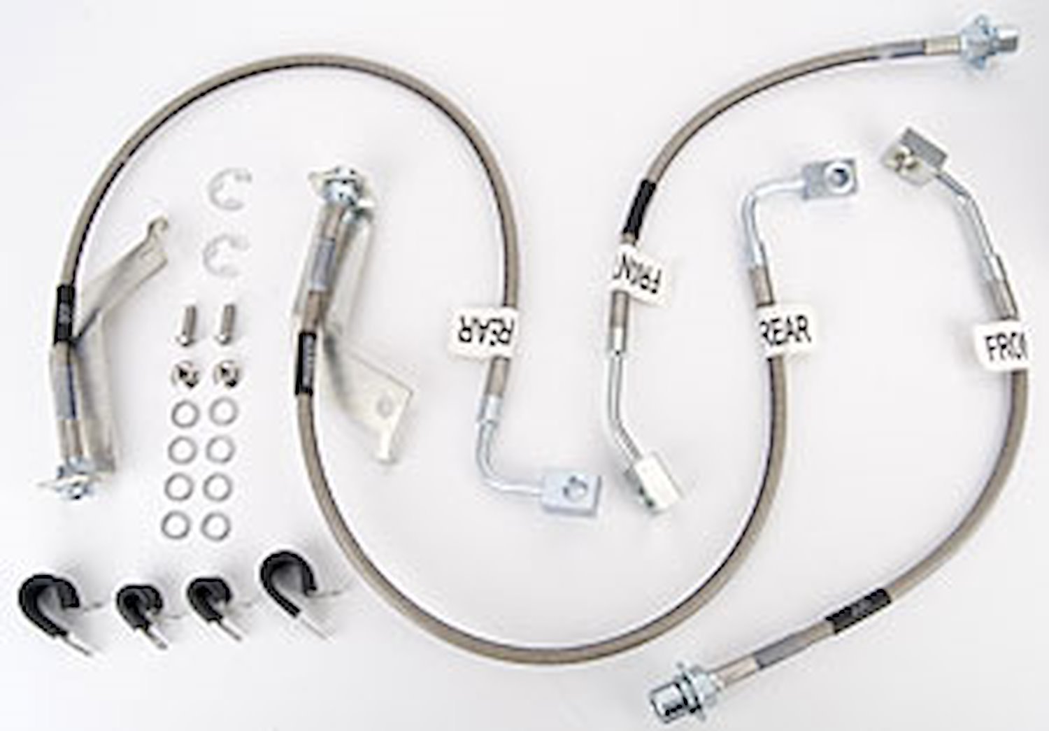
To swap rear springs on an IRS-equipped Cobra or IRS-swapped Mustang is very easy. Remove the exhaust, remove the two lower shock bolts, put a jack under the center rear of the IRS subframe, and remove the two rear IRS subframe bolts. Then just lower the jack until you can pull the springs out. Anyways, when we were raising the IRS back up after removing the springs, it slipped off the jack and dropped down, and it overextended the left rear brake line. The line started leaking brake fluid, so basically the car is undriveable until the line is replaced. Today I located a set of Russell braided stainless brake lines that I should have in my hands tomorrow. The kit has lines for all 4 corners. I'll do the rears because they are necessary (can't do just one), but I might not do the fronts if we run out of time.
799-693270.jpg


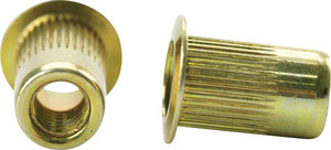
We also had to think of a solution for attaching the sensors, because they are being mounted on the rear framerail. It's like a 2"x3" (roughly) hollow steel section, so our options are either to drill out both sides to gain access for a nut on the back side, or use a Nutsert. We decided to try the Nutsert option, and Michel was tasked with trying to find some locally today. I haven't talked to him, so I don't know if he found some. For those that don't know what a Nutsert is, here is a pic and a link:
0125615.jpg

Fastenal Nutsert

I emailed Mike at Accuair with a few questions we had about the ride height sensors. We needed to know what happens if we go beyond the oft-repeated 2.75" maximum travel for the sensors. With our current setup, which is the only option we have anyways, we have roughly 3" of travel at the sensor. The sensor allows for almost 4" of travel between the physical stops, but Mike says there's some kind of dead spot at either end of the range that the sensor won't be able to read properly. I guess we'll have to see what happens when the car gets out on the road.

That's all for now. Tomorrow I have to go buy a couple things we will need, and I should have my brakelines in by mid-afternoon as well. Stay tuned.
 

Fastphil

Bagged.
Established Member
Joined
Feb 13, 2006
Messages
1,153
Location
Ste-Marthe-sur-le-Lac, QC
We got a late start today, but we feel we made some good progress, and we have a clear view of what needs to be done tomorrow, so we should get some good progress tomorrow too. I have a deadline of Friday night in sight because of the yearly All-Ford show on Saturday.

Michel finished working on the rear ride height sensor plates today, and they look and work great! The driver side is bolted onto the car and checked off the to-so list. The passenger side was still too tacky to work with, so we'll let it dry overnight. Michel shot them with black header paint, followed by a coat of rubberized undercoating. This will help to prevent them from rusting, and reduce rattling should they ever come loose.
P1030404.jpg

P1030405.jpg

P1030426.jpg


We also made a final adjustent to the ride height sensor positioning to get the travel more centered in the sensors' range, and I got my hands on some Nutserts from the shop at my work. They will do the job perfectly, but the tool that installs them is missing a key component, so Michel fabbed up something that will do the job. We will try it first thing tomorrow. I got my brake lines today and installed the rears right away, just to get something checked off the to-do list. We just have to bleed the brakes after we swap out the front lines.
P1030409.jpg

P1030431.jpg


Moving on to bigger items, I started working on the wiring harness for the ECU and air compressors. Two wires (Ignition and Lighting) needed to be routed from the ECU to under the dash, so I ran them along the main wiring harness on the driver side floor. Tomorrow I will tap them into the wires near the fuse panel and that will be done. Michel ran the wiring harness for the Touchpad Controller down the center of the car. I don't have a permanent location in mind for the Touchpad yet, so for now it will reside in front of the shifter.
P1030422.jpg

P1030427.jpg

P1030428.jpg

P1030425.jpg


I also mocked up the positioning of the air tank and compressors. The main restriction is the length of the braided stainless lines that go from the compressors to the tank. I know I could always get longer ones, but I'm sure they cost more than I'm willing to spend. We ended up mounting the compressors on the inner fenderwells. Michel deemed it necessary to fabricate some more mounting plates for the compressors, so he got to work on that while I was fiddling with the wiring harnesses. I think the location we chose for the compressors will look really cool once it's done. We will probably have to cut clearance holes in the side panels of the trunk liner to clear the heads of the compressors, so they'll be peeking into the trunk but not fully visible.
P1030413.jpg

P1030410.jpg

P1030411.jpg

P1030419.jpg

P1030420.jpg

P1030432.jpg


Another thing I took care of was to assemble the top plates for the front airbags. Couple of washers and nuts and an air fitting on each, and they're ready to go into the car.
P1030417.jpg


As I stated, we have a clear idea of what we will do tomorrow. First on the list is to get the rear suspension buttoned up. We also need to get the air system up and running so we can get the car on the ground and turned around in the garage.
 

earico

It's 4:20 somewhere...
Established Member
Joined
Jan 13, 2011
Messages
5,168
Location
SA TX
Damnit Phil! You almost made me throw up my sushi dinner! :xpl:

Here I am relaxed on the couch just scrolling through your latest post...roll the mouse wheel a little more.....OMG WTF! Then I see big, hairy, plumber crack on my 50" tv in my living room!!! :lol1:

Oh and nice work by the way. Not my style but I respect the quality work. :rockon:
 
Last edited:

oldmodman

Well-Known Member
Established Member
Joined
Jun 27, 2003
Messages
16,543
Location
West Los Angeles
First time I have seen anyone post up a full description of all the toil involved in installing a system like this.
Lots of fabrication required to get it the way you want.
Not exactly what I would call a 'drop in" kit.
I can just imagine how it would get installed at a "typical hack shop" that so many people seem to take their cars to.
But you and your friend are doing a first rate installation.

Have you test fired the compressors to see how much noise and vibration they produce? I saw a similar system installed in a car at SEMA and the compressors were double shock mounted. They had been rubber mounted to a plate, and the plate was rubber shock mounted to the vehicle. And that eliminated almost all the sound and vibration they produced.

Keep adding to your thread. I will keep watching, for sure.
 

Fastphil

Bagged.
Established Member
Joined
Feb 13, 2006
Messages
1,153
Location
Ste-Marthe-sur-le-Lac, QC
Damnit Phil! You almost made me throw up my sushi dinner! :xpl:

Here I am relaxed on the couch just scrolling through your latest post...roll the mouse wheel a little more.....OMG WTF! Then I see big, hairy, plumber crack on my 50" tv in my living room!!! :lol1:

Oh and nice work by the way. Not my style but I respect the quality work. :rockon:

What's a project without a little silliness! Thanks for the compliment.

First time I have seen anyone post up a full description of all the toil involved in installing a system like this.
Lots of fabrication required to get it the way you want.
Not exactly what I would call a 'drop in" kit.
I can just imagine how it would get installed at a "typical hack shop" that so many people seem to take their cars to.
But you and your friend are doing a first rate installation.

Have you test fired the compressors to see how much noise and vibration they produce? I saw a similar system installed in a car at SEMA and the compressors were double shock mounted. They had been rubber mounted to a plate, and the plate was rubber shock mounted to the vehicle. And that eliminated almost all the sound and vibration they produced.

Keep adding to your thread. I will keep watching, for sure.

You'll get to see a video later on where you can hear the compressors running, but before the setup is completed. As you may know, the car is (mostly) done, and the sound of the compressors isn't too annoying. They only run when I play with the switches a lot anyways. I have been idly investigating ways to make them quieter, but for now it'll stay the way it is. Thanks for your interest!
 

Fastphil

Bagged.
Established Member
Joined
Feb 13, 2006
Messages
1,153
Location
Ste-Marthe-sur-le-Lac, QC
First time I have seen anyone post up a full description of all the toil involved in installing a system like this.
Lots of fabrication required to get it the way you want.
Not exactly what I would call a 'drop in" kit.
I can just imagine how it would get installed at a "typical hack shop" that so many people seem to take their cars to.
But you and your friend are doing a first rate installation.

Have you test fired the compressors to see how much noise and vibration they produce? I saw a similar system installed in a car at SEMA and the compressors were double shock mounted. They had been rubber mounted to a plate, and the plate was rubber shock mounted to the vehicle. And that eliminated almost all the sound and vibration they produced.

Keep adding to your thread. I will keep watching, for sure.

The beauty of such a project is the fact that you can (and should) do as much custom work with is as you want. The whole point, after all, is to take your car to the next level, so you might as well do it the way you want the first time. We took the time to figure out how to install things so that they would be removable (except for a few holes of course) for future serviceability and any changes or upgrades we would want to make.

I never even considered having a shop install it because it was beyond my budget. After we were finished, I began to look at other people's air setups. Specialized shops do good work (at a price), private owners like myself have off-the-wall creative ideas, and other shops do real hack jobs. In the end, I'm glad we did it ourselves, because we now know exactly what went into it, how to do these things, and what to do should anything ever go wrong. It was an experience I will remember for the rest of my life. Thanks for your interest, ad stay tuned for the rest of the build!
 

Fastphil

Bagged.
Established Member
Joined
Feb 13, 2006
Messages
1,153
Location
Ste-Marthe-sur-le-Lac, QC
Today we got a lot of work done, but we didn't get the rear end off the jacks, and the front is still on the ground. We did complete a few tasks that will enable us to get the front done a little quicker.

I started off by finishing the wiring under the dash, and I put the interior trim pieces back in place. I also worked on the wiring for the compressor relay. I decided to mount it on a metal tab on the driver side between the rear seat and the trunk, where everything else except the tank is going. It's starting to get crowded in there, but I don't expect to have to go in there anyways. I ran the big power wire for the compressors from the battery to the relay along the underside of the car, and brought it up through the grommet that the ABS sensor passes through.
P1030448.jpg

P1030449.jpg

P1030453.jpg


We finally got the rear suspension all back together, and we had to extend the pushrods because the shock absorber was forcing the A-arms lower than they were when we mocked it up. The shocks also reduced the top of the travel slightly, so it worked out well. We added the brake line clamps to the same single bolt that holds Michel's fabricated plates to the upper A-arms, making it a simple and clean setup. The Nutserts for the sensors worked like a charm with Michel's fabricated installation tool.
P1030436.jpg

P1030439.jpg

P1030440-1.jpg


Michel's fabricated compressor brackets were all painted and ready to go into the car, so we got them installed.
P1030450.jpg

P1030463.jpg


We polished up the exhaust tips while they were off the car and made a couple of small fitment adjustments to the exhaust system when we put it back on the car. The girls came by to lend a helping hand. It's fun to have them around in the shop, they came in handy when running the big power wire through the front inner fender and up through the grommet!
P1030442.jpg

P1030443.jpg


Accuair's products are really top-notch. If the wiring harnesses weren't all properly labeled and with different, non-interchangeable connectors on them, I'd have a hell of a time keeping track of what's what. Every time we run a harness or air line through sheetmetal or near sharp edges, we use our trusty red air hose. Also, to pass the sensor harnesses through these holes, it's necessary to dismantle the connectors and pass the wires through the hole then put the connectors back on when you're ready to plug them in. Here you can see the pair of front sensor harnesses disappearing through the trunk floor to be routed forwards together under the car along the fuel lines. The other two holes have an air line each, with each line running up its own side of the car. The passenger side line follows the fuel lines as well, while the driver side follows the big red power wire.
P1030462.jpg

P1030467.jpg

P1030474.jpg

P1030469.jpg

P1030476.jpg

P1030475.jpg


I also got all the air tank fittings in place with teflon tape. Michel has an idea for a tank mounting bracket, because it can't be bolted straight to the floor due to its location partially over the spare tire well.
P1030470.jpg


We noticed that my right front tire is worn unevenly down to the cords on the inner edge while we were under the car. We'll have to investigate the cause of that. A new tire (or two) and possibly a ball joint wasn't on my to-do list (or in my budget), but safety first.

Tomorrow will be a big day. We are still aiming to get it done for Saturday's show, but I won't be too sad if I don't make it. As long as I can get to my family BBQ on Saturday afternoon, I'll be happy. I'll stop making predictions as to what we will be doing tomorrow. I could just sum it up by saying that tomorrow, we need to do everything that's not done yet.

Later.
 

Users who are viewing this thread


Top