Vortech v3 installation on my 02 GT, not entirely sure how my PCV/Vacuum Lines should be connecting with the Aftercooler/Catch can

droptop2v

New Member
Established Member
Joined
Feb 10, 2024
Messages
10
Location
vegas
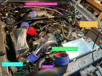
Not quite sure how my PCV/Vacuum lines should be connected, even more so with my new catch can installed. Staring at these 20 year old manual photos for a while now, it seems like my IAC should connect to my inlet duct, and my PCV lines need to connect to the 2 plastic bungs at the end, but with my catch can do I just do my passenger to the can and have the driver side connect to my inlet? In which case I have an extra 'bung' that needs to be plugged?

Additionally Im not sure about the 2(?) bypass valves, looking at both manuals it seems like there's one where my IAC used to connect on the discharge pipe that goes into my throttle body, and another under my inlet duct which I think is suppose to connect to the after cooler bung?

I've dug through stangnet, svt performance, google, reddit blahblahbklah I'm feeling like I'm 1 of 20 who got the aftercooler kit and 1 of 1 who isn't able to understand these connections.

Months of work is nearly complete, just need to figure out these last 2 tidbits before I hookup the water cooling.

If anyone is familiar or understands these connections, I'm all ears...

I can post more pics/videos if need be.
 

Attachments

  • VacuumLineMagic.png
    VacuumLineMagic.png
    3.3 MB · Views: 250

2003RedfireVert

Male and Female He created them.
Established Member
Joined
Jan 25, 2022
Messages
2,490
Location
Fly over country
IMG_0236.jpeg

Here is my procharger setup on my old GT. IAC went to the intake pipe.

This was a blow through setup. Blow off valve vented to atmosphere.

My Catch can, bottom right of the picture, was modified after this photo. I T-ed both lines together and ran that line to the inlet of the catch can, vented the other side to the atmosphere. The way it’s setup in the photo made a major vacuum leak.
 

droptop2v

New Member
Established Member
Joined
Feb 10, 2024
Messages
10
Location
vegas
Thats how mines setup, but its also what Morosso wants in the instructions. Mines not a blowthrough, my MAF is down connected to the filter under my fender.

I'm gonna be using an after market amazon coupler to connect the MAF to the plastic 90 degree elbow that goes to the plastic inlet pipe on the head unit.

The instructions from Vortech, albiet accurate, are very hard to understand at times. Even more so to someone whos a long time weekend warrior at best.

Install Docs for the Power cooler:

https://static.summitracing.com/global/images/instructions/8n301030im.pdf

General install manual:

https://cdn.shopify.com/s/files/1/0780/8575/files/4FL020-010v4.2_MANUAL_4.6_2V_MUSTANG_GT.pdf?677

I'm a pictures guy, the pictures in these are rough to follow.

With your blowthrough setup having those plastic bungs on your inlet aren't an issue from my understanding since the MAF is at the end just before the intake. With mine being on after the MAF im supposed to connect them to vacuum lines which makes sense, I'm just not sure how they should flow/routed.

I believe the driver side PCV is meant to go in one and the IAC into another, but that still leaves the third smaller bung in question still. Unless that's where the passenger side PCV goes...but with the catch can added into the route that would mean I have to connect the outlet of the catch can to that smaller bung intake?

In this case only the passenger side would have a route to the catch can (which should be okay for a temporary setup?).
 

trueblue03gt

Member
Established Member
Joined
Jul 3, 2022
Messages
98
Location
Seattle, WA
Just went over those instructions for you. As I understand, the passenger side catch can may or may not have a check valve in it. I know you don't want air blowing back through the catch can. If you have the check valve vortech provides with the kit, you should ensure it goes AFTER the catch can, while it's on its way into the throttle body bung.

As for the other tubes... the area you highlighted turquoise houses your IAC and PCV system. They're two different sizes, so match the right-sized hose to right right-sized bung. As for the two bypass valves, I don't think that's stock for the Vortech Aftercooled system. There should be only one, between the intercooler and the discharge of the blower, that connects to the intake pipe. You can probably just use two anyway though, or you could plug it up. It looks like someone drilled a hole in your intake pipe so that they could screw another bung in. Did you buy this kit brand new, and if so, from whom? I'm seeing images all over the internet, and NONE of them show that bung between the aftercooler and the throttle body.

Sorry to break you the bad news. If you have any other questions, I just went through all this crap, so please message me. I included some images that make me believe your piping has been modified.
img_1640_882d097d18ef0f170f6e487f997e85d0c5396215.jpg
Screenshot 2024-02-12 231908.png
Screenshot 2024-02-12 231919.png
 

droptop2v

New Member
Established Member
Joined
Feb 10, 2024
Messages
10
Location
vegas
Just went over those instructions for you. As I understand, the passenger side catch can may or may not have a check valve in it. I know you don't want air blowing back through the catch can. If you have the check valve vortech provides with the kit, you should ensure it goes AFTER the catch can, while it's on its way into the throttle body bung.

As for the other tubes... the area you highlighted turquoise houses your IAC and PCV system. They're two different sizes, so match the right-sized hose to right right-sized bung. As for the two bypass valves, I don't think that's stock for the Vortech Aftercooled system. There should be only one, between the intercooler and the discharge of the blower, that connects to the intake pipe. You can probably just use two anyway though, or you could plug it up. It looks like someone drilled a hole in your intake pipe so that they could screw another bung in. Did you buy this kit brand new, and if so, from whom? I'm seeing images all over the internet, and NONE of them show that bung between the aftercooler and the throttle body.

Sorry to break you the bad news. If you have any other questions, I just went through all this crap, so please message me. I included some images that make me believe your piping has been modified. View attachment 1828649View attachment 1828648View attachment 1828647
This is a brand new kit from Vortech directly I bought in late October. The instructions mention connecting the second bypass valve, which honestly threw me off I thought they just sent a second since the kit has a lot of 'extras' for the other variants (bullit/cobras etc).

I believe there's check valves on both valve covers, I just have the hoses running straight from there. Ill dm ya with some extras, Im ready to get this bish running
 

trueblue03gt

Member
Established Member
Joined
Jul 3, 2022
Messages
98
Location
Seattle, WA
This is a brand new kit from Vortech directly I bought in late October. The instructions mention connecting the second bypass valve, which honestly threw me off I thought they just sent a second since the kit has a lot of 'extras' for the other variants (bullit/cobras etc).

I believe there's check valves on both valve covers, I just have the hoses running straight from there. Ill dm ya with some extras, Im ready to get this bish running
Interesting. Then you’ll connect both of the bypasses. You can always call Vortech, they’re pretty helpful. I’m not sure which you’re supposed to connect to be honest. I can’t lie though, I don’t see where the two bypass valves will go. Anywhere I look, I don’t see another bypass included in the kit.

I think only the passenger side has a check valve, so be careful when on the drivers side.
 

droptop2v

New Member
Established Member
Joined
Feb 10, 2024
Messages
10
Location
vegas

trueblue03gt

Member
Established Member
Joined
Jul 3, 2022
Messages
98
Location
Seattle, WA

On page 23 Image 10-G you can see the second bypass by the in intake manifold. Page 22 you can see they're asking for the Bypass below the plastic inlet (looks like you have an anderson power pipe on yours) to be routed back into the bung on the powercooler, is that how yours is routed?
I run a blow-through, so I have a blow-off valve, and I don't have stock vortech piping. Although, it looks like the bypass post-IC should go on the side of the intake piping, as shown in 10-F. The bypass pre-IC should go under the intake piping, by where the intake for the blower is.
 

Users who are viewing this thread


Top