OK. Had a chance to run the feed and return lines today and mount the filter.
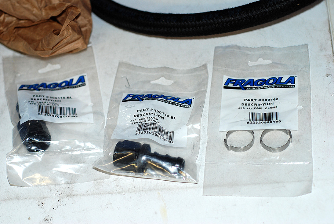
Over all, the new PTFE fittings were relatively easy to assemble.
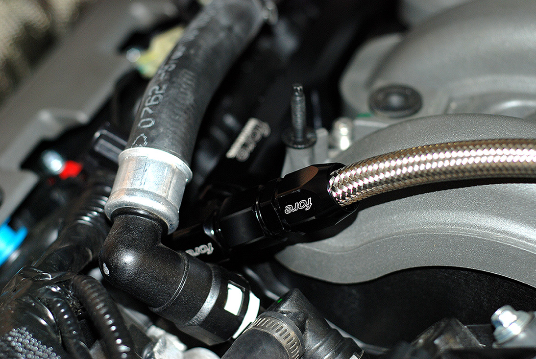
Got to try a sample PTFE line with the black "Conductive Carbon" inner core. This is approved for air craft and will not degrade over time or cause static like other PTFE line.

First step is to pull back the stainless steel so you have room for the Olive connector.

Next I installed the Olive between the stainless and PTFE inner hose.

Then I put the end fitting into my soft jaws in my vise with very little pressure and pushed on the hose to the fitting.

Then I turned the hose so it was facing up in the vise and tightened the fitting down with a 7/8" socket and ratchet.

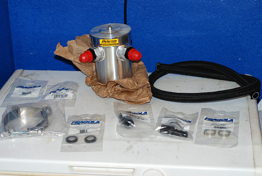
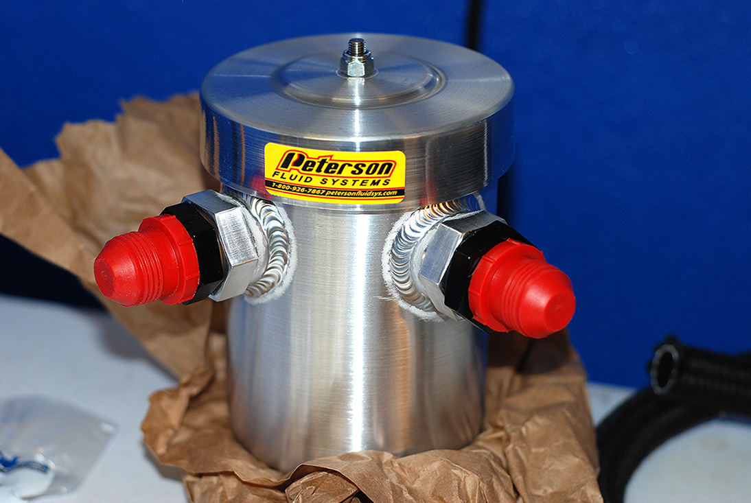
Next up was to mount the filter. The filter comes with self tapping screws, but the floor pan where I wanted to mount it was very thick. So I drilled and tapped it.

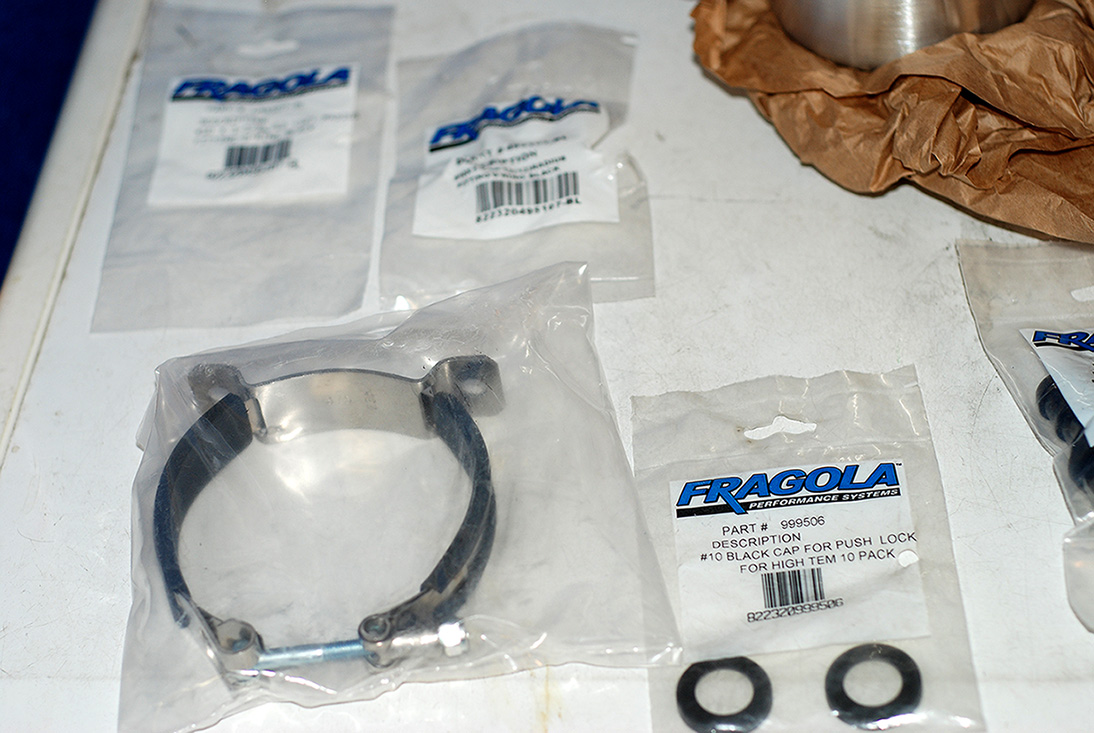
Here are the screws I used to secure it to the bottom of the car.

I decided to mount the filter right behind the rocker panel on the drivers side for easy serviceability.

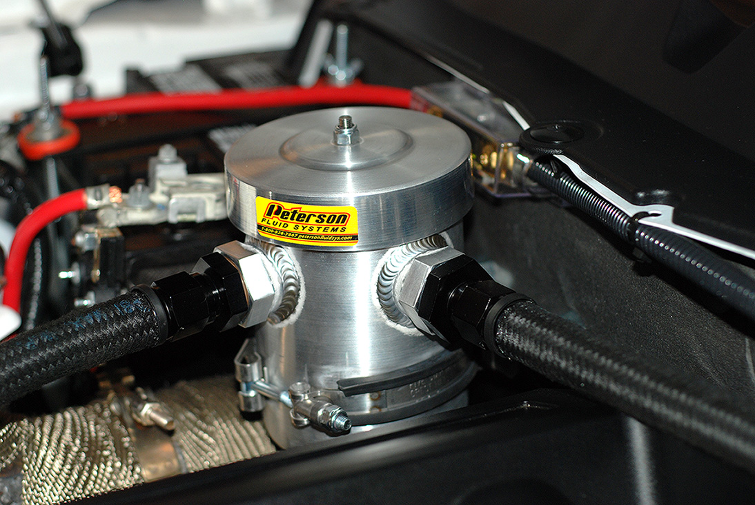
Here are the hoses hooked up to the hat.

I just followed the factory routings for ease of installation. Here's where it runs down from the front corner of the tank.

There are two plastic factory guards under the car that help protect the lines and I chose to run the hose under like the factory. You can see where I ran the feed line out for the filter.


Here I used another supplied cushion clamp and ran the line back under the factory panel.

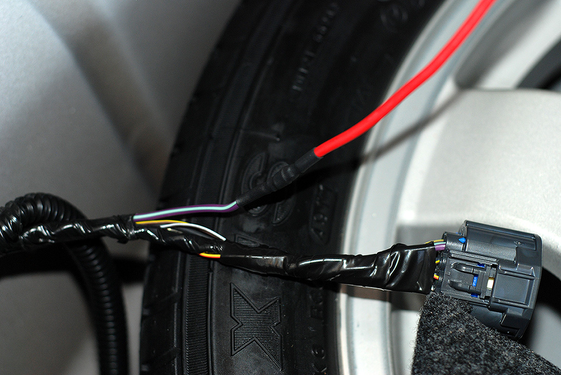
Here is where the lines runs up the inner wheel well following the factory lines.

Then up into the engine bay behind the drivers side strut tower. I taped off the ends so nothing would get into them.

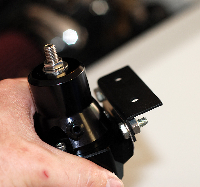
For the regulator, I decided to fab up a quick mount to work with the mount on the regulator.

Since the sound tube was deleted, this left two existing holes for the bracket.

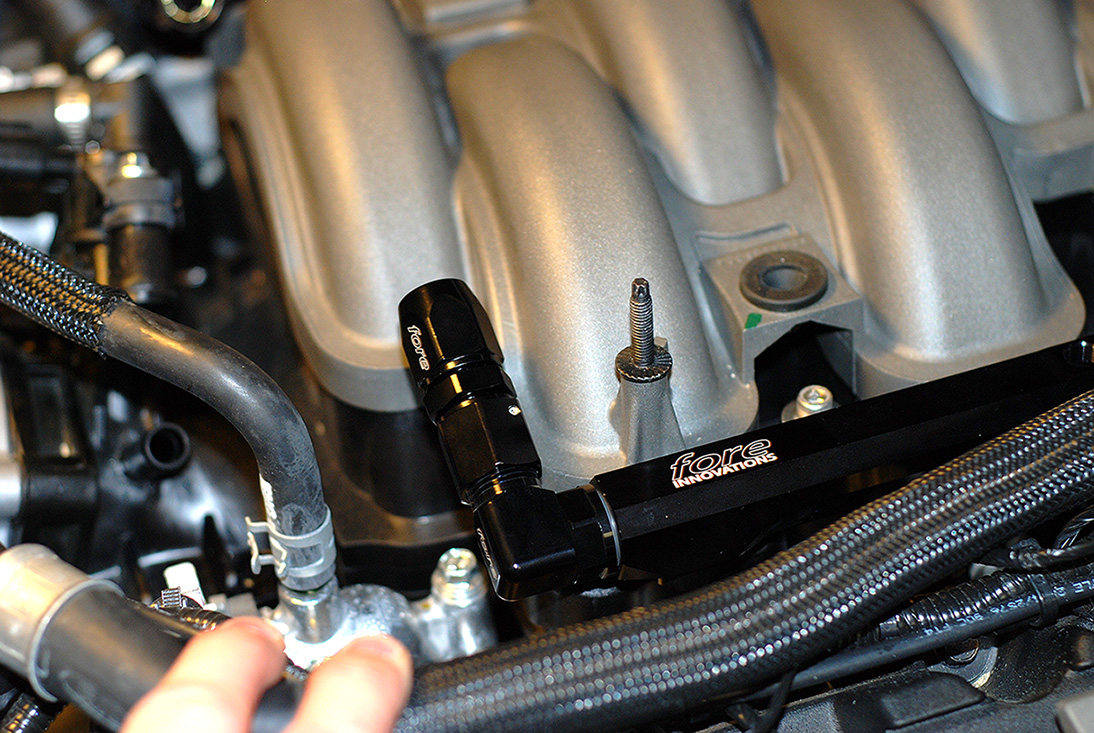
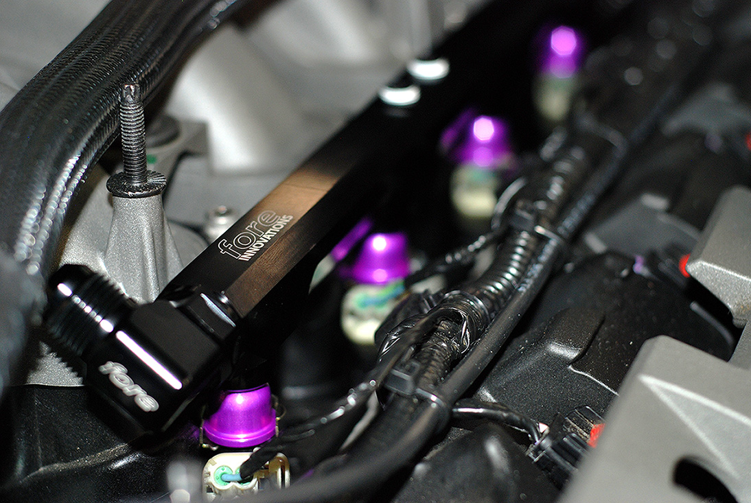
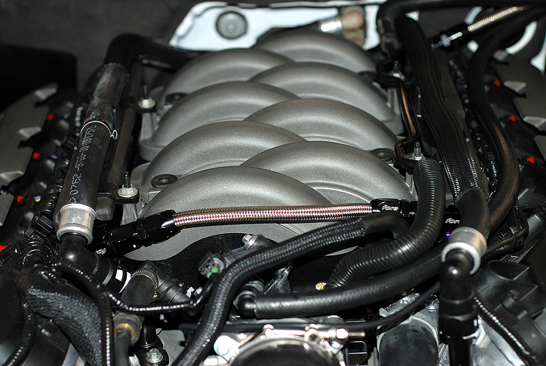
Now I just have to run the hoses to the rails and install the injectors! :-D
Over all, the new PTFE fittings were relatively easy to assemble.
Got to try a sample PTFE line with the black "Conductive Carbon" inner core. This is approved for air craft and will not degrade over time or cause static like other PTFE line.
First step is to pull back the stainless steel so you have room for the Olive connector.
Next I installed the Olive between the stainless and PTFE inner hose.
Then I put the end fitting into my soft jaws in my vise with very little pressure and pushed on the hose to the fitting.
Then I turned the hose so it was facing up in the vise and tightened the fitting down with a 7/8" socket and ratchet.
Next up was to mount the filter. The filter comes with self tapping screws, but the floor pan where I wanted to mount it was very thick. So I drilled and tapped it.
Here are the screws I used to secure it to the bottom of the car.
I decided to mount the filter right behind the rocker panel on the drivers side for easy serviceability.
Here are the hoses hooked up to the hat.
I just followed the factory routings for ease of installation. Here's where it runs down from the front corner of the tank.
There are two plastic factory guards under the car that help protect the lines and I chose to run the hose under like the factory. You can see where I ran the feed line out for the filter.
Here I used another supplied cushion clamp and ran the line back under the factory panel.
Here is where the lines runs up the inner wheel well following the factory lines.
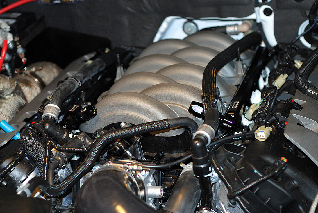
Then up into the engine bay behind the drivers side strut tower. I taped off the ends so nothing would get into them.
For the regulator, I decided to fab up a quick mount to work with the mount on the regulator.
Since the sound tube was deleted, this left two existing holes for the bracket.
Now I just have to run the hoses to the rails and install the injectors! :-D
Last edited: