A slight deviation from the core subject, I know, so I'll correlate it to the "and what not" portion from this thread's title. That being, now is the perfect time for some kind of front tow hook. Plus, I was asked.:idea: So deviate I shall!
It was less than a year ago when I sold my complete set of 2010 coupe wheels/tires to fellow SVTP member mblgjr (Matt). I had just picked up a fresh set of '11 PP wheels/tires so I made the switch one afternoon. There was a light dusting of snow falling onto the ground when I rolled the now removed '10 set from my shop to my home garage for clean up prior to boxing and shipping. Man I miss those wheels...

Anyhoo, I had pulled my car out of the barn with its new rolling stock and parked it on the frozen tundra just off to the side of the barn. There was less than an inch of light powder. Didn't matter. I knew I was stuck the moment I stopped moving.

The car would do nothing but slide - zero traction. What was really frustrating was there was no real spot to use for an attachment point for a tow strap. Not in the front or in the rear. I made a mental note at that point to do something. So I started collecting information I could find on the web on tow points on an S197 chassis car.
I noticed that FRPP offered a bumper that had a fabricated attachment point for a hook.

Ford Racing Performance Parts
No longer available as well as requiring the front bumper to be cut for fitment. Cross that one off the list. But it brought to my attention the hook or "loop" that FRPP offered.
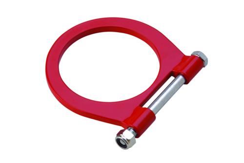
Ford Racing Performance Parts
The loop seemed like a nice enough part. The issue would be how to attach. Then I found a few threads I had passed over either at TS or here. There was a gentleman selling a fabricated bracket that allowed using FRPP's loop and you didn't have to slash through the front bumper to use it. He had a drop bracket fabbed up that would go through the lower grille.


Looked to be fairly robust, as seen on this non-GT500

Here's the bracket being added to a GT500


I'm not exactly big on the single shear attachment bolt-in method, the fact that a side load may cause it to rotate, nor having to trim the lower grille.


I do like the fact that you can simply remove the loop bolt to take the actual loop off w/o having to partially disassemble the front clip to get at it.

I'm considering incorporating a removeable threaded forged eyebolt that could easily thread into a nut that would be flush with the grille and not require cutting it.
If all goes as planned, I'll fire up the plasma cutter at work and whip something up. That is why I'm not finishing the H/E install just yet.
Thanks a million. Your are the man. Now I have a chance of getting this feat done. Thanks again for the picture and detail information and I understand it...

")

